
Datasheet
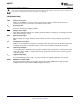
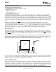
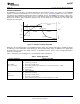

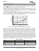
Table Of Contents
- FEATURES
- APPLICATIONS
- GENERAL DESCRIPTION
- ABSOLUTE MAXIMUM RATINGS
- DC THRESHOLDS
- RECOMMENDED DC OPERATING CONDITIONS
- IMPEDANCE
- TIMING
- TYPICAL CHARACTERISTICS
- REVISION HISTORY

200
160
180
140
120
100
80
60
40
20
4
3
2
1
2 4 6 8 10 50 100 150 200 250
R -k
MTO
W
Pulsewidth-ms
ShowsTolerance
bq2000T
SLUS149D –MAY 1999–REVISED JANUARY 2010
www.ti.com
Once top-off is started, the timer is reset and top-off proceeds until the timer expires, V
MCV
is reached, or there is
a temperature fault. During top-off, current is delivered to the battery in pulses that occur each second. The fixed
pulse width allows an average current of 1/16 of the fast charge current to be delivered to the battery every
second. The LED is always off during top-off and trickle maintenance charge.
During top-off, there are three different temperature faults that can occur. If V
TS
> V
LTF
, top-off is suspended, the
timer is paused, and trickle charge is started. When V
TS
falls below V
LTF
, top-off is resumed. If V
TS
< V
HTF
, all
charging stops, but the timer keeps counting. When V
TS
> V
HTF
, top-off is resumed, if there is still time remaining
on the timer. If there is not time left, trickle maintenance charge is entered. If V
TS
< V
TCO
, all charging stops. Only
trickle maintenance charge may resume after V
TS
> V
HTF
.
Following top-off, the bq2000T trickle-charges the battery by enabling the MOD pin to charge at a rate of once
every 1.0 second. The trickle pulse-width is user-selectable and is set by the value of the resistor R
MTO
,
connected between the RC pin and V
SS
. Figure 7 shows the relationship between the trickle pulse-width and the
value of R
MTO
. The typical tolerance of the pulsewidth below 150 kΩ is ±10%.
Figure 7. Relationship Between Trickle Pulse-Width and Value of R
MTO
Note that with an R
MTO
value around 150 kΩ, the trickle charge pulse width is nearly identical to the top-off pulse
width of 62.5 ms (1/16 of a second for a 1A fast charge current). With R
MTO
values near 150 kΩ, it can be difficult
to tell which state the IC is in (top-off or trickle charge). The best way to tell if the bq2000T is in top-off or trickle
charge is to look at the RC pin when the temperature is between the LTF and HTF. In top-off, the RC pin is
counting and has a sawtooth waveform on it. In trickle charge, there is no timer and the RC pin is at a DC value.
The RC pin contains valuable information in determining what state the bq2000T is in, since it always operates in
one of three modes. If the RC pin is low (around V
SS
potential), the IC is in sleep mode. (If the RC pin is low for
brief instants during fast charge, the bq2000T is sampling the TS pin for ΔT/Δt). If the RC pin is at some DC
value (usually around 1 V to 2 V), then the IC has paused the timer or the timer is inactive. If the RC pin is a
sawtooth waveform (similar to Figure 15), then the timer is running and the RC pin is considered “active.” Lastly,
the RC pin can be loaded by too large of a C or too small of an R. This sometimes makes the usual sawtooth
waveform look like a triangle waveform on an oscilloscope (the rise time is lengthened), or the RC signal could
have the appearance of being clipped (flat top or bottom). The timer is unreliable under these conditions and the
bq2000T should not be operated in this manner. Table 2 summarizes the different states of the RC pin.
Table 2. RC Pin Status
bq2000T CHARGE STATE TS PIN STATE RC PIN BEHAVIOR
Battery absent N/A 1-V to 2-V DC level
Sleep mode N/A Ground (V
SS
)
Charge qualification (including battery
conditioning (trickle charge) and charge N/A 1-V to 2-V DC level
suspended)
10 Submit Documentation Feedback Copyright © 1999–2010, Texas Instruments Incorporated
Product Folder Link(s): bq2000T