
Datasheet
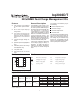


Note: This resistor-divider network input impedance to
end-to-end should be at least 200kΩ and less than 1 MΩ.
A ground-referenced negative temperature coefficient ther-
mistor placed in proximity to the battery may be used as a
low-cost temperature-to-voltage transducer. The tempera-
ture sense voltage input at TS is developed using a
resistor-thermistor network between V
CC
and V
SS
. See
Figure 1.
Starting A Charge Cycle
Either of two events starts a charge cycle (see Figure 5):
1. Application of power to V
CC
or
2. Voltage at the BAT pin falling through the maximum
cell voltage where
V
MCV
=2V±5%
If the battery is within the configured temperature and
voltage limits, the IC begins fast charge. The valid bat-
tery voltage range is V
BAT
<V
MCV
. The valid tempera-
ture range is V
HTF
<V
TS
<V
LTF
for the bq2002T and
V
HTF
<V
TS
for the bq2002D where
V
LTF
= 0.4 ∗ V
CC
±5%
V
HTF
= 0.25 ∗ V
CC
±5% (bq2002T only)
If the battery voltage or temperature is outside of these
limits, the IC pulse-trickle charges until the tempera-
ture falls within the allowed fast charge range or a new
charge cycle is started.
Fast charge continues until termination by one or more of
the four possible termination conditions:
Rate of temperature rise
Maximum voltage
Maximum temperature
Maximum time
T/ t Termination
The bq2002D/T samples at the voltage at the TS pin ev-
ery 19s and compares it to the value measured three
samples earlier. If the voltage has fallen 25.6mV or
more, fast charge is terminated. The ∆T/∆t termination
test is valid only when V
TCO
<V
TS
<V
LTF
for the
bq2002T and V
TCO
<V
TS
for the bq2002D.
Temperature Sampling
A sample is taken by averaging together 16 measure
-
ments taken 570µs apart. The resulting sample period
(18.18ms) filters out harmonics around 55Hz. This tech
-
4
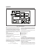
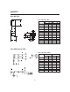
bq2002D/T
OSC
TM
CC
LED
V
CC
V
SS
BAT
INH
Clock
Phase
Generator
Timing
Control
Sample
History
A to D
Converter
MCV
Check
Power
Down
TS
Bd2002TD.eps
Voltage
Reference
Power-On
Reset
TCO
Check
HTF/
LTF
Check
Charge-Control
State Machine
T/ t
ALU
Figure 4. Block Diagram