
Datasheet
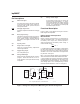


Starting A Charge Cycle
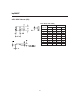
Either of two events startsachargecycle(seeFigure4):
1.Applicationofpowerto V
CC
or
2. Voltage at the BAT pin falling through the maximum
cell voltage V
MCV
where
V
MCV
= 2V ±5%.
If the battery is within the configured temperature and
voltage limits, the IC begins fast charge. The valid bat-
tery voltage range is V
BAT
<V
MCV
. The valid tempera-
ture range is V
TS
>V
TCO
where
V
TCO
= 0.5 ∗ V
CC
±5%.
If the battery voltage or temperature is outside of these
limits, the IC pulse-trickle charges until the next new
charge cycle begins.
Fast charge continues until termination by one or more of
the five possibleterminationconditions:
n
Peak voltage detection (PVD)
n
Negative delta voltage (-
∆
V)
n
Maximum voltage
n
Maximum temperature
n
Maximum time
4
bq2002/F
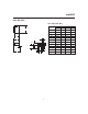
Corresponding
Fast-Charge
Rate TM Termination
Typical Fast-Charge
and Top-Off
Time Limits
(minutes) Typical PVD
and -
∆
V Hold-Off
Time (seconds)
Top-Off
Rate
Pulse-
Trickle
Rate
Pulse-
Trickle
Period
(ms)
bq2002 bq2002F
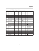
C/2 Mid PVD 160 160 600 C/32 C/64 9.15
1C Low PVD 80 100 300 C/16 C/64 18.3
2C High -
∆
V 40 40 150 Disabled C/32 18.3
Notes: Typical conditions = 25°C, V
CC
= 5.0V.
Mid = 0.5
*
V
CC
±
5V
Tolerance on all timing is
±
20%.
Table 1. Fast-Charge Safety Time/Hold-Off Table
TD2002F1.eps
Fast ChargingV
CC
= 0 Fast Charging
CC Output
LED
s
s
Charge initiated by application of power
Charge initiated by battery replacement
Pulse-TrickleTop-Off
(optional)
286
See
Table 1
s
286
4576
Figure 4. Charge Cycle Phases