
Datasheet


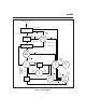


Functional Description
Figure 3 shows a state diagram and Figure 4 shows a
block diagram of the bq2003.
Battery Voltage and Temperature
Measurements
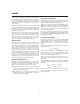
Battery voltage and temperature are monitored for
maximum allowable values. The voltage presented on
the battery sense input, BAT, should represent a
single-cell potential for the battery under charge. A
resistor-divider ratio of:
RB1
RB2
= N - 1
is recommended to maintain the battery voltage within
the valid range, where N is the number of cells, RB1 is
the resistor connected to the positive battery terminal,
and RB2 is the resistor connected to the negative bat
-
tery terminal. See Figure 1.
Note: This resistor-divider network input impedance to
end-to-end should be at least 200kΩ and less than 1MΩ.
A ground-referenced negative temperature coefficient
thermistor placed in proximity to the battery may be used
as a low-cost temperature-to-voltage transducer. The tem
-
perature sense voltage input at TS is developed using a re
-
sistor-thermistor network between V
CC
and battery’s nega
-
tive terminal See Figure 1. Both the BAT and TS inputs
are referenced to SNS, so the signals used inside the IC are:
V
BAT
-V
SNS
=V
CELL
and
V
TS
-V
SNS
=V
TEMP
3
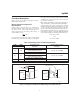
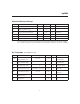
Table 1. New Charge Cycle and Discharge Stimulus
CCMD DCMD New Charge Cycle
Started by:
Discharge-Before-Charge
Started by:
Pulled Up/Down to:
V
SS
V
SS
V
CC
rising to valid level
A rising edge on DCMD
Battery replacement
(V
CELL
falling through V
MCV
)
A rising edge on CCMD
V
CC
V
CC
V
CC
rising to valid level
A rising edge on DCMD
Battery replacement
(V
CELL
falling through V
MCV
)
A falling edge on CCMD or DCMD
V
CC
V
SS
A rising edge on CCMD A rising edge on DCMD
V
SS
V
CC
A falling edge on CCMD A rising edge on DCMD
bq2003
Fg2003a2.eps
N
T
C
bq2003
V
CC
PACK +
PACK -
T
S
SNS
RT1
RT2
RB2
RB1
bq2003
V
DC
External Trickle Resistor Negative Temperature
Coefficient Thermister
Pass Element
PACK+
PACK-
MOD
BAT
SNS
Figure 1. Voltage and Temperature Monitoring and Trickle Resistor