
Datasheet


Discharge-Before-Charge
The DCMD input is used to command discharge-before-
charge via the DIS output. Once activated, DIS becomes
active (high) until V
CELL
falls below V
EDV,
at which time
DIS goes low and a new fast charge cycle begins. See
Table 1 for the conditions that initiate discharge-before-
charge. Discharge-before-charge is qualified by the
same voltage and temperature conditions that qualify a
new charge cycle start (see below). If a discharge is ini
-
tiated but the pack voltage or temperature is out of
range, the chip enters the charge pending mode and
trickle charges the battery until the voltage and tem
-
perature qualification conditions are met, and then
starts to discharge.
Starting A Charge Cycle
The stimulus required to start a new charge cycle is de
-
termined by the configuration of the CCMD and DCMD
inputs. If CCMD and DCMD are both pulled up or
pulled down, then a new charge cycle is started by (see
Figure 2):
1. V
CC
rising above 4.5V
2. V
CELL
falling through the maximum cell voltage,
V
MCV
.V
MCV
is the voltage presented at the MCV
input pin, and is configured by the user with a re-
sistor divider between V
CC
and ground. The al-
lowed range is 0.2 to 0.4 ∗ V
CC
.
3. A rising edge on CCMD if it is pulled down, or a fal
-
ling edge on CCMD if it is pulled up.
Starting a new charge cycle may be limited to a push-
button or logical pulse input only by pulling one member
of the DCMD and CCMD pair up while pulling the other
input down. In this configuration a new charge cycle
will be started only by a falling edge on CCMD if it is
pulled up, and by a falling edge on CCMD if it is pulled
down. See Table 1.
If the battery is within the configured temperature and
voltage limits, the IC begins fast charge. The valid bat
-
tery voltage range is V
EDV
<V
BAT
<V
MCV
where:
V
EDV
= 0.2 ∗ V
CC
± 30mV
The valid temperature range is V
HTF
<V
TEMP
<V
LTF
,
where:
V
LTF
= 0.4 ∗ V
CC
± 30mV
V
HTF
= [(1/8 ∗ V
LTF
) + (7/8 ∗ V
TCO
)] ± 30mV
V
TCO
is the voltage presented at the TCO input pin, and is
configured by the user with a resistor divider between V
CC
and ground. The allowed range is 0.2 to 0.4 ∗ V
CC
.
If the temperature of the battery is out of range, or the
voltage is too low, the chip enters the charge pending
state and waits for both conditions to fall within their
allowed limits. There is no time limit on the charge
pending state; the charger remains in this state as long
as the voltage or temperature conditons are outside of
4
bq2003
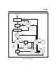
Fast Charging Top-Off
(Optional)
34 sec.
TD200301a.eps
Discharge
(Optional)
Charge
Pending
DIS
MOD Switch-Mode Configuration
MOD External Regulation
(SNS Grounded)
CHG Status Output
TEMP Status Output
Charge cycle start.
Battery outside temperature limits.
or
Battery within temperature limits.
Battery discharged to 0.2 V
CC
.
4
sec
.
Figure 2. Charge Cycle Phases