
Datasheet


Functional Description
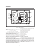
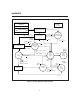
Figure 2 shows a block diagram and Figure 3 shows a
state diagram of the bq2004E/H.
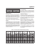
Battery Voltage and Temperature
Measurements
Battery voltage and temperature are monitored for
maximum allowable values. The voltage presented on
the battery sense input, BAT, should represent a
two-cell potential for the battery under charge. A
resistor-divider ratio of:
RB1
RB2
=
N
2
- 1
is recommended to maintain the battery voltage within
the valid range, where N is the number of cells, RB1 is
the resistor connected to the positive battery terminal,
and RB2 is the resistor connected to the negative bat
-
tery terminal. See Figure 1.
Note: This resistor-divider network input impedance to
end-to-end should be at least 200kΩ and less than 1MΩ.
A ground-referenced negative temperature coefficient ther-
mistor placed in proximity to the battery may be used as a
low-cost temperature-to-voltage transducer. The tempera-
ture sense voltage input at TS is developed using a
resistor-thermistor network between V
CC
and V
SS
. See
Figure 1. Both the BAT and TS inputs are referenced to
SNS, so the signals used inside the IC are:
V
BAT
-V
SNS
=V
CELL
and
V
TS
-V
SNS
=V
TEMP
Discharge-Before-Charge
The DCMD input is used to command discharge-before-
charge via the DIS output. Once activated, DIS becomes
active (high) until V
CELL
falls below V
EDV,
at which time
DIS goes low and a new fast charge cyclebegins.
The DCMD
input is internally pulled up to V
CC
(its inac
-
tive state). Leaving the input unconnected, therefore,
results in disabling discharge-before-charge. A negative
going pulse on DCMD
initiates discharge-before-charge
at any time regardless of the current state of the
bq2004. If DCMD
is tied to V
SS
, discharge-before-charge
will be the first step in all newly started charge cycles.
Starting A Charge Cycle
A new charge cycleisstartedby:
1. Application of V
CC
power.
2. V
CELL
falling through the maximum cell voltage,
V
MCV
where:
V
MCV
= 0.8 ∗ V
CC
± 30mV
3. A transition on the INH
input from low to high.
If DCMD
is tied low, a discharge-before-charge will be
executed as the first step of the new charge cycle. Oth-
erwise, pre-charge qualification testing will be the first
step.
The battery must be within the configured temperature
and voltage limits before fast charging begins.
The valid battery voltage range is V
EDV
<V
BAT
<V
MCV
where:
V
EDV
= 0.4 ∗ V
CC
± 30mV
3
bq2004E/H
Fg2004a.eps
N
T
C
bq2004E/H
V
CC
PACK +
PACK -
T
S
SNS
RT1
RT2
RB2
RB1
bq2004E/H
Negative Temperature
Coefficient Thermister
PACK+
PACK-
BAT
SNS
Figure 1. Voltage and Temperature Monitoring