
Datasheet


The valid temperature range is V
HTF
<V
TEMP
<V
LTF
,
where:
V
LTF
= 0.4 ∗ V
CC
± 30mV
V
HTF
= [(1/3 ∗ V
LTF
) + (2/3 ∗ V
TCO
)] ± 30mV
V
TCO
is the voltage presented at the TCO input pin, and is
configured by the user with a resistor divider between V
CC
and ground. The allowedrangeis0.2to0.4∗ V
CC
.
If the temperature of the battery is out of range, or the
voltage is too low, the chip enters the charge pending
state and waits for both conditions to fall within their al
-
lowed limits. During the charge-pending mode, the IC
first applies a top-off charge to the battery.
The top-off charge, at the rate of
18
of the fast charge,
continues until the fast-charge conditions are met or the
top-off time-out period is exceeded. The IC then trickle
charges until the fast-charge conditions are met. There
is no time limit on the charge pending state; the charger
remains in this state as long as the voltage or tempera
-
ture conditons are outside of the allowed limits. If the
voltage is too high, the chip goes to the battery absent
state and waitsuntilanewchargecycleisstarted.
Fast charge continues until termination by one or more
of the six possible termination conditions:
n
Delta temperature/delta time (∆T/∆t)
n
Peak voltage detection (PVD)
n
Negative delta voltage (-
∆
V)
n
Maximum voltage
n
Maximum temperature
n
Maximum time
PVD and -∆V Termination
The bq2004E/H samples the voltage at the BAT pin once
every 34s. When -∆V termination is selected, if V
CELL
is
lower than any previously measured value by 12mV
±4mV (6mV/cell), fast charge is terminated. When PVD
termination is selected, if V
CELL
is lower than any previ
-
ously measured value by 6mV ±2mV (3mV/cell), fast
charge is terminated. The PVD and -∆V tests are valid
in the range 0.4 ∗ V
CC
<V
CELL
< 0.8 ∗ V
CC
.
4
bq2004E/H
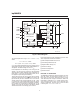
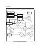
BD200401.eps
Timing
Control
OSC
Display
Control
Charge Control
State Machine
Discharge
Control
MOD
Control
TCO
Check
LTF
Check
A/D
EDV
Check
MCV
Check
DIS MOD INH V
CC
V
SS
BAT
SNS
TS
TCOTM2TM1
LED1
DCMD
DVEN
V
TS
- V
SNS
V
BAT
- V
SNS
LED2
DSEL
PWR
Control
Figure 2. Block Diagram