
Datasheet


Functional Description
General Operation
The bq2010 determines battery capacity by monitoring
the amount of charge input to or removed from a re
-
chargeable battery. The bq2010 measures discharge and
charge currents, estimates self-discharge, monitors the
battery for low-battery voltage thresholds, and compen
-
sates for temperature and charge/discharge rates. The
charge measurement derives from monitoring the voltage
across a small-value series sense resistor between the
negative battery terminal and ground. The available bat
-
tery charge is determined by monitoring this voltage over
time and correcting the measurement for the environ
-
mental and operating conditions.
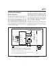
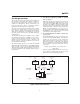
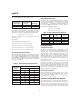
Figure 1 shows a typical battery pack application of the
bq2010 using the LED display capability as a charge-
state indicator. The bq2010 can be configured to display
capacity in either a relative or an absolute display mode.
The relative display mode uses the last measured dis
-
charge capacity of the battery as the battery “full” refer
-
ence. The absolute display mode uses the programmed
full count (PFC) as the full reference, forcing each seg
-
ment of the display to represent a fixed amount of
charge. A push-button display feature is available for
momentarily enabling the LED display.
The bq2010 monitors the charge and discharge currents
as a voltage across a sense resistor (see R
S
in Figure 1).
A filter between the negative battery terminal and the
SR pin may be required if the rate of change of the bat
-
tery current is too great.
3
bq2010
FG201001.eps
SEG
6
/PROG
6
SEG
5
/PROG
5
SEG
4
/PROG
4
SEG
3
/PROG
3
SEG
2
/PROG
2
SEG
1
/PROG
1
SR
DISP
SB
V
CC
REF
bq2010
Gas Gauge IC
LCOM
V
SS
EMPTY
DQ
V
CC
C1
0.1 F
µ
Q1
ZVNL110A
R
1
R
S
RB
1
RB
2
Load
Charger
Indicates optional.
Directly connect to V
CC
across 3 or 4 cells (3 to 5.6V nominal)
with a resistor and a Zener diode to limit voltage during charge.
Otherwise, R1, C1, and Q1 are needed for regulation of >4 cells.
The value of R1 depends on the number of cells.
Programming resistors (6 max.) and ESD-protection diodes are not shown.
R-C on SR ma
y
be re
q
uired
,
application-specific.
V
CC
Figure 1. Battery Pack Application Diagram—LED Display