! " # $ # # # % &' ( # ) '* ( # ! ( User’s Guide January 2003 PMP Portable Power SLUU132A
IMPORTANT NOTICE Texas Instruments Incorporated and its subsidiaries (TI) reserve the right to make corrections, modifications, enhancements, improvements, and other changes to its products and services at any time and to discontinue any product or service without notice. Customers should obtain the latest relevant information before placing orders and should verify that such information is current and complete.
EVM IMPORTANT NOTICE Texas Instruments (TI) provides the enclosed product(s) under the following conditions: This evaluation kit being sold by TI is intended for use for ENGINEERING DEVELOPMENT OR EVALUATION PURPOSES ONLY and is not considered by TI to be fit for commercial use.
EVM WARNINGS AND RESTRICTIONS It is important to operate this EVM within the input voltage range of 5.6 V and the output voltage range of 0 V and 4.25 V. Exceeding the specified input range may cause unexpected operation and/or irreversible damage to the EVM. If there are questions concerning the input range, please contact a TI field representative prior to connecting the input power.
Contents Contents 1 Introduction . . . . . . . . . . . . . . . . . . . . . . . . . . . . . . . . . . . . . . . . . . . . . . . . . . . . . . . . . . . . . . . . . . . . . 1-1 1.1 Background . . . . . . . . . . . . . . . . . . . . . . . . . . . . . . . . . . . . . . . . . . . . . . . . . . . . . . . . . . . . . . . . 1-2 1.2 Performance Specification Summary . . . . . . . . . . . . . . . . . . . . . . . . . . . . . . . . . . . . . . . . . . 1-2 2 Test Summary . . . . . . . . . . . . . . . . . . . . . . .
Contents vi
Chapter 1 Introduction This user’s guide describes the bq24013 (bqTINY) evaluation module. The EVM provides a convenient method for evaluating the performance of a charge-management solution for portable applications using the bq24013 product family. A complete designed and tested charger is presented. The charger is designed to deliver up to 1.0 A of continuous charge current, but is programmed for 0.7 A, for single-cell Li-Ion or Li-Pol applications using a dc power supply. Topic Page 1.
Background 1.1 Background The bqTINY series are highly integrated Li-Ion and Li-Pol linear charge-management devices targeted at space-limited portable applications. In a small package, the bqTINY series offer integrated PowerFET and current sensor, reverse blocking diode, high-accuracy current and voltage regulation, charge status, and charge termination. The bqTINY charges the battery in three phases: conditioning, constant current, and constant voltage. Charge terminates on the basis of minimum current.
Chapter 2 Test Summary This chapter describes the test setups used and the tests performed in evaluating the EVM. Setup: The bq24013 EVM board requires a single-cell Li-Ion or Li-Pol battery pack and a 5-VDC, 1-A power source to provide input power. The test setup connections and jumper setting selections are configured for a stand-alone evaluation but can be changed to interface with external hardware, such as a microcontroller. Topic Page 2.1 I/O and Jumper Connections . . . . . . . . . . . . . . . .
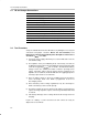
I/O and Jumper Connections 2.1 I/O and Jumper Connections Jack Connect To: J1–DC+ Power supply positive, preset to 5.
Test Procedure Another way to briefly see each mode on a scope is to connect a 1-mF capacitor and a 10-kΩ resistor on the output in place of a battery to observe the power-up and cycling between voltage regulation and fast charge via the refresh threshold. Note: Because of the battery-detection circuit, it is not possible to switch-in static load resistors to jump between regulation and constant-current modes. An alternate procedure described below uses a dynamic load to replace the battery circuit.
Test Procedure 2.2.2 Equipment Setup 1) Connect the load board to the BAT+ and BAT–. Set SW1 through SW4 in the closed position. 2) Connect a voltage meter to the BAT+/BAT– output to monitor the output voltage (range 0 to 5 V). 3) Set the lab supply for 5.1 V ±0.1VDC, 1.0 ±0.1 A current limit, and then turn off the supply. Connect the source supply to a current meter and to J1, noting polarity. (You may use an internal source current meter if it has 5% or better accuracy.
Chapter 3 Schematic, Physical Layouts, and Bill of Materials This chapter contains the schematic diagram, the board layouts and assembly drawings, and the bill of materials required for the EVM. Topic Page 3.1 Schematic . . . . . . . . . . . . . . . . . . . . . . . . . . . . . . . . . . . . . . . . . . . . . . . . . . . . 3-2 3.2 Physical Layouts . . . . . . . . . . . . . . . . . . . . . . . . . . . . . . . . . . . . . . . . . . . . . . 3-3 3.3 Bill of Materials . . . . . . . . . . . . . . . . . .
2 3 4 R1 1.5 kΩ 5 R2 1.5 kΩ D1 Red IN OUT VCC BAT STAT1 STAT2 VSS TTE PWP 1 2 11 C3 0.47 µF D2 Green CE ISET 10 4 9 3 8 2 7 6 R3 C1 1 µF 10 V C2 1 µF 10 V 1 R4 1.13 kΩ TP2 R5 10 kΩ J3 1 4 3 2 1 3 2 1 J4 J5 Not installed BAT– J2 3 1 TTE 1 2 LED EXT STAT2 JUMPER BAT– TP1 1 R6 10 kΩ LED EXT STAT1 JUMPER BAT+ STAT1 STAT2 DC– CE Schematic DC– 1 3.1 Schematic DC+ Figure 3–1.
Physical Layouts 3.2 Physical Layouts 3.2.1 Board Layout Figure 3–2 shows the assembly view of the EVM. Figure 3–3 shows the top layer. Figure 3–4 shows the bottom layer. Figure 3–2.
Physical Layouts Figure 3–3. Top Layer Figure 3–4.
Bill of Materials 3.3 Bill of Materials Table 3–1 lists materials required for the EVM. Table 3–1. Bill of Materials Ref Des Item# bq24013 Size MFR Part Number 1 0 C1 Capacitor, ceramic, X5R, 1 µF, 10 V Description 805 Panasonic ECJ-2YB1A105K 2 1 C2 Capacitor, ceramic, X5R, 1 µF, 10 V 805 Panasonic ECJ-2YB1A105K 3 1 C3 Capacitor, ceramic, X7R, 0.47 µF, 16 V 805 Panasonic ECJ-2YB1C474K 4 1 D1 Diode, LED, red, 1.