
Datasheet


2.3.1 Four Quadrant Power Supply
2.3.2 Large Capacitor
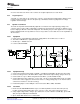
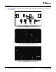
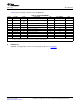
2.3.3 Dynamic Load Board
2.3.3.1 Equipment
+
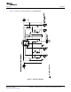
2.3.3.2 Equipment Setup
2.3.3.3 Procedure
www.ti.com
Test Summary
A source meter that can sink or source current can easily be adjusted to test each mode.
To briefly see each mode on an oscilloscope, connect a 1-mF capacitor in parallel with a 20-k Ω resistor,
from the output to ground, to observe the power up, termination, and then cycling between voltage
regulation and fast charge.
The loads are dynamic and automatically adjusted as a function of the output (battery) voltage. The
sequence of the test procedure is important to remain in the desired mode. If altered, no damage occurs,
but one might get different results than anticipated. The following test procedure applies more to verifying
that the EVM was built correctly and does not test every feature. See the data sheet for an explanation of
all the features.
1. Power source: current-limited 5-V laboratory supply with its current limit set to 1 A ± 0.1 A
2. Two Fluke 75 Multimeters, equivalent or better.
3. Oscilloscope – TDS220 or better
4. Load Test Board: PR694
1. Connect the load board to the BAT+ and BAT–. Set SW1 through SW4 in the ON (closed) position.
2. Connect a voltage meter to the BAT+/BAT– output to monitor the output voltage (range is 0-to-5 V).
3. Connect CH1 of scope to BAT+ and ground lead to BAT– (1 V/div and 200 ms/div).
4. Set the laboratory power supply for 5.1 V ± 0.1 Vdc, 1-A ± 0.1-A current limit and then turn off supply.
Connect the source supply to a current meter and to J1, noting polarity (may use an internal source
current meter if it has 5% or better accuracy).
5. Install shunt jumpers on the LED pins 1 and 2 of headers JMP1, JMP2, and JMP3.
1. Ensure that the EQUIPMENT SETUP steps are followed {switches must be in the ON (closed)
position, shunts installed, and power source set to 5.1 V ± 0.1 Vdc}. Turn on the power source.
2. Verify output voltage, BAT+, charges up to between 2 V to 2.9 V and the red LED (D1), green LED
(D2), and green LED (D3) are illuminated.
3. Open switch SW2 and then close switch SW2.
SLUU315 – June 2008 bq24083 1-A, Single-Cell Li-Ion and Li-Polymer Charge Management IC EVM 3
Submit Documentation Feedback