
Datasheet


2.4 Ordering Information
Test Summary
www.ti.com
4. Verify that output voltage BAT+ settles between 3.2 V to 4 V.
5. Verify that the LED (D2) turns off.
6. Verify that the input current is between 0.65 A to 0.75 A.
7. Open switch SW3.
8. Verify that the input current is between 70 mA and 160 mA.
9. Verify the output voltage BAT+ is between 4.15 V dc and 4.25 Vdc.
10. Place shunt on JMP5 (4.1 V) and verify output voltage BAT+ is between 4 Vdc and 4.1 Vdc.
11. Place shunt on JMP4 (CHG DISABLE), and verify input current is less than 10 mA.
12. Remove JMP4 shunt (place on only one pin of JMP4 to keep from losing the shunt).
13. Open switch SW2.
14. Verify with a scope (250 ms/div, 1 V/div) that output BAT+ charges and discharges between the
maximum limits of 3.3 V and 4.25 V with a period of between 600 ms to 1500 ms.
15. Verify that the LEDs flash between RED (D1) and GREEN (D2).
16. Close switches SW2 and SW3 (all switches should be closed now), and power down supply.
17. EVM is good if all tests have passed. Remove I/O connections.
18. If more EVMs are to be tested, loop back to 7.1 and continue until all units have been tested.
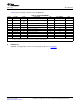
Table 3. Ordering Information
EVM Part Number Additional Devices Chemistry Pack Voltage Capacity
bq24083EVM None Li-Ion / Li-Poly 2.5 V to 4.2 V Any
4 bq24083 1-A, Single-Cell Li-Ion and Li-Polymer Charge Management IC EVM SLUU315 – June 2008
Submit Documentation Feedback