
Datasheet


User's Guide
SLUU476–December 2010
bq24133EVM Stand-Alone Synchronous, Switch-Mode,
Battery-Charge Controller With Integrated N-MOSFETs
and Power Path Selector
This user's guide describes the features and operation of the bq24133EVM Evaluation Module (EVM). The
EVM assists users in evaluating the bq24133 synchronous battery charger. The EVM is also called the
HPA715A. The manual includes the bq24133EVM bill of materials, board layout, and schematic.
Contents
1 Introduction .................................................................................................................. 2
1.1 EVM Features ...................................................................................................... 2
1.2 General Description ................................................................................................ 2
1.3 I/O Description ...................................................................................................... 2
1.4 Control and Key Parameters Settings ........................................................................... 3
1.5 Recommended Operating Conditions ........................................................................... 3
2 Test Summary ............................................................................................................... 5
2.1 Definitions ........................................................................................................... 5
2.2 Safety ................................................................................................................ 5
2.3 Quality ............................................................................................................... 5
2.4 Safety Apparel ...................................................................................................... 5
2.5 Equipment ........................................................................................................... 6
2.6 Equipment Setup ................................................................................................... 6
2.7 Procedure ........................................................................................................... 7
3 PCB Layout Guideline ...................................................................................................... 9
4 Bill of Materials, Board Layout, and Schematic ....................................................................... 10
4.1 Bill of Materials .................................................................................................... 10
4.2 Board Layout ...................................................................................................... 12
4.3 Schematic ......................................................................................................... 18
List of Figures
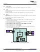
1 Original Test Setup for HPA715A (bq24133EVM)...................................................................... 6
2 Top Assembly.............................................................................................................. 12
3 Top Layer................................................................................................................... 13
4 Second Layer .............................................................................................................. 14
5 Third Layer ................................................................................................................. 15
6 Bottom Layer............................................................................................................... 16
7 Bottom Assembly .......................................................................................................... 17
8 bq24133EVM Schematic ................................................................................................. 18
List of Tables
1 I/O Description............................................................................................................... 2
2 Control and Key Parameters Settings.................................................................................... 3
3 Recommended Operating Conditions .................................................................................... 3
4 Bill of Materials............................................................................................................. 10
1
SLUU476–December 2010 bq24133EVM Stand-Alone Synchronous, Switch-Mode, Battery-Charge
Controller With Integrated N-MOSFETs and Power Path Selector
Submit Documentation Feedback
© 2010, Texas Instruments Incorporated