
Datasheet


1520 R
V
I
ISET
CHARGE
´
=
www.ti.com
Introduction
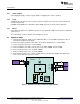
1.4 Control and Key Parameters Settings
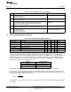
Table 2. Control and Key Parameters Settings
Jack Description Factory Setting
JP1 Select external TS input or internal valid TS setting Jumper ON 1-2 (external TS)
1-2 : External TS input
2-3 : Internal valid TS setting
JP2 The pullup power source supplies the LEDs when JP2 is ON. LED has no power Jumper ON (LED power available)
source when JP2 is OFF.
JP3 TTC setting Jumper OPEN (enable timer and
2-3 : Connect TTC to VREF to enable termination and disable timer termination)
1-2 : Connect TTC to GND to disable termination and disable timer
OPEN : Enable timer and termination
JP4 Charger enable/disable setting. ISET is pulled to GND and the charger is Jumper OPEN (disable charger)
disabled when JP4 OPEN; charger is enabled when JP4 is ON.
JP5 CELL selection Jumper ON 1-2 (1 CELL) -001
1-2 : CELL-GND, 1CELL Jumper ON 2-3 (3 CELL) -002
2-3 : CELL-VREF, 3CELL
OPEN: CELL- FLOAT, 2CELL
1.5 Recommended Operating Conditions
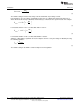
Table 3. Recommended Operating Conditions
Symbol Description Min Typ Max Unit Notes
Supply voltage, V
BUS
Input voltage 4.5 8 V 001
Supply voltage, V
BUS
Input voltage 6 18 V 002
Battery voltage, V
BAT
Voltage applied at VBAT terminal of J2 2.1 4.2 V 001
Battery voltage, V
BAT
Voltage applied at VBAT terminal of J2 2.1 12.6 V 002
Supply current Maximum input current 0 5 A
Charge current, I
chrg
Battery charge current 0 2 2.5 A
Operating junction temperature range, T
J
0 125 °C
The bq2410 EVM board requires a regulated supply approximately 1 V minimum above the regulated
voltage of the battery pack to a maximum input voltage of 16 Vdc. The bq24133 uses the CELL pin to
select the number of cells with a fixed 4.2 V/cell. Connecting CELL to AGND gives a 1-cell configuration, a
floating CELL pin gives a 2-cell configuration, and connecting to VREF gives a 3-cell configuration. The
CELL pin adjusts the internal resistor voltage divider from the BAT pin to AGND pin for voltage feedback
and regulate to internal 2.1-V voltage reference.
CELL Pin Voltage Regulation
AGND 4.2V
Floating 8.4V
VREF 12.6V
For Note 001, the BAT voltage is set to 4.2 V and for Note 002, the BAT voltage is set to 12.6 V.
The ISET input sets the maximum charging current. Battery current is sensed by current sensing resistor
R
SR
connected between SRP and SRN. The full-scale differential voltage between SRP and SRN is 40 mV
maximum. The equation for charge current is:
(1)
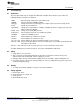
For bq24133, the precharge current is set as 1/10 of the fast-charge rate set by ISET voltage, according to
the formula
3
SLUU476–December 2010 bq24133EVM Stand-Alone Synchronous, Switch-Mode, Battery-Charge
Controller With Integrated N-MOSFETs and Power Path Selector
Submit Documentation Feedback
© 2010, Texas Instruments Incorporated