
Datasheet


VIN
J1
PGND
VSYS
J2
PGND
VBAT
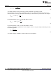
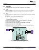
APPLICATION CIRCUIT
TP2
SW
U1
V
Iin
I
Power supply
#1
Iout
V
Isys
V
I
Load #1
Load #2
I
TS_EXT
/STAT
JP2
TEST POINTS
D1
JP3
JP4
CE
TTC
LED
SETTINGS
JP5JP1
LEDPWR
bq24133EVM
HPA715A
Test Summary
www.ti.com
2.5 Equipment
2.5.1 Power Supplies
Power Supply #1 (PS#1): a power supply capable of supplying 30 V at 5 A is required.
2.5.2 Loads
LOAD#1 A 30-V (or greater), 5-A (or greater) electronic load that can operate at constant current and
constant voltage mode.
LOAD#2: An HP 6060B 3-V to 60-V/0-A to 60-A, 300-W system dc electronic load or equivalent.
2.5.3 Meters
Seven Fluke 75 multimeters (equivalent or better) or four equivalent voltage meters and three equivalent
current meters.
The current meters must be capable of measuring 5-A+ current.
2.6 Equipment Setup
1. Set the Power Supply #1 (PS#1) for 6-V ±200-mVdc (001), or 16-V ±0.200-mV (002),4.5-A ±0.1-A
current limit, and then turn off supply.
2. Connect the output of PS#1 in series with a current meter (multimeter) to J1 (VIN, PGND).
3. Connect a voltage meter across J1 (VIN, PGND).
4. Connect Load#1 in series with a current meter to J2 (VBAT, PGND). Turn off Load#1.
5. Connect Load#2 in series with a current meter to J2 (VSYS, PGND). Turn off Load#2.
6. Connect a voltage meter across J2 (VBAT, PGND).
7. Connect a voltage meter across J2 (VSYS, PGND).
8. Check all jumper shunts. JP1: connect 2-3 (External TS); JP2: ON; JP3: OPEN; JP4: OPEN. JP5:
connect 1-2 for 001 and connect 2-3 for 002.
Figure 1. Original Test Setup for HPA715A (bq24133EVM)
6
bq24133EVM Stand-Alone Synchronous, Switch-Mode, Battery-Charge SLUU476–December 2010
Controller With Integrated N-MOSFETs and Power Path Selector
Submit Documentation Feedback
© 2010, Texas Instruments Incorporated