
Datasheet


75.0 mm
SMBD
SMBC
PWR084 Rev. B
VSS
12.0 mm
PACK +
RT1
GND
COMMONLED2LED4
HEATER
CNTRL
1P
PACK -CE
PRES
SYS
LED1LED3LED5
FUSE
RT2
4P
3P
2P
1N
TB7
TB1
TB5
TB6
2.5V
1
1
1
C1
C3
C4
C27
C23
C17
C25
C20
C2
C6
C19
C18
C26
C28
C14
D1
D11
D2
D4
D10
D8
D9
Q6
R1
R15
R22
R10
R18
R16
R28
R31
R25
R24
R40
R8
R2
R32
R4
R29
R42
R35
R30
RT1
TB3
TB7
TB6
TP1
SW1
D3
D6
D7
RT2
Q4
R7
C29
J1
TP2
TB1 TB2
T 4B
TB5
U1
Circuit Module Physical Layouts and Bill of Materials
www.ti.com
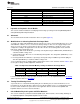
4.1 Board Layout
This section shows the dimensions, PCB layers (Figure 1 through Figure 5), and assembly drawings for
the bq20z655 and bq34z651 modules.
Figure 1. bq20z655EVM and bq34z651EVM Layout—Silk Screen
Figure 2. Top Assembly
Figure 3. Top Layer
Figure 4. Bottom Layer
4
bq20z655EVM and bq34z651EVM SBS 1.1 Impedance Track SLUU697– November 2011
Technology-Enabled Evaluation Module
Submit Documentation Feedback
Copyright © 2011, Texas Instruments Incorporated