
Datasheet


®
BUF634
9
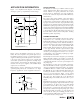
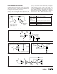
HIGH FREQUENCY APPLICATIONS
The BUF634’s excellent bandwidth and fast slew rate make it
useful in a variety of high frequency open-loop applications.
When operated open-loop, circuit board layout and bypassing
technique can affect dynamic performance.
For best results, use a ground plane type circuit board layout
and bypass the power supplies with 0.1µF ceramic chip
capacitors at the device pins in parallel with solid tantalum
10µF capacitors. Source resistance will affect high-frequency
peaking and step response overshoot and ringing. Best
response is usually achieved with a series input resistor of
25Ω to 200Ω, depending on the signal source. Response
with some loads (especially capacitive) can be improved
with a resistor of 10Ω to 150Ω in series with the output.
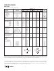
OP AMP RECOMMENDATIONS
OPA177, OPA1013 Use Low I
Q
mode. G = 1 stable.
OPA111, OPA2111
OPA121, OPA234
(1)
,
OPA130
(1)
OPA27, OPA2107 Low I
Q
mode is stable. Increasing C
L
may cause
OPA602, OPA131
(1)
excessive ringing or instability. Use Wide BW mode.
OPA627, OPA132
(1)
Use Wide BW mode, C
1
= 200pF. G = 1 stable.
OPA637, OPA37 Use Wide BW mode. These op amps are not G = 1
stable. Use in G > 4.
NOTE: (1) Single, dual, and quad versions.
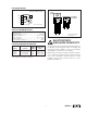
OPA
NOTE: (1) C
1
not required
for most common op amps.
Use with unity-gain stable
high speed op amps.
V
IN
V
O
V+
V–
BUF634
C
1
(1)
Wide BW mode
(if required)
BW
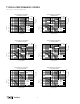
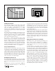
FIGURE 5. High Performance Headphone Driver.
FIGURE 8. Bridge-Connected Motor Driver.
1/2
OPA2234
9kΩ
BUF634
1kΩ
V
IN
±1V
Motor
1/2
OPA2234
BUF634
10kΩ
10kΩ
±20V
at 250mA
FIGURE 7. Current-Output Valve Driver.
OPA177
BUF634
Valve
V
IN
±2V
10Ω
I
O
= ±200mA
FIGURE 4. Boosting Op Amp Output Current.
C
(1)
C
(1)
pseudo
ground
+
12V
–
BUF634
10kΩ
10µF
+24V
10kΩ
+
12V
–
NOTE: (1) System bypass capacitors.
+
FIGURE 6. Pseudo-Ground Driver.
OPA132
Drives headphones
or small speakers.
5kΩ
BUF634
100kΩ
1µF
R
L
= 100Ω
f
1kHz
20kHz
THD+N
0.015%
0.02%
250Ω
G = +21
V
IN
V–
BW
V+