CC2533 RF4CE Basic Development Kit Hardware User’s Guide SWRU266
swru266 Table of Contents 1 2 3 4 4.1 4.2 4.3 4.4 4.5 4.6 4.7 5 5.1 5.2 5.3 6 6.1 INTRODUCTION................................................................................................................. 4 ABOUT THIS MANUAL...................................................................................................... 4 ACRONYMS AND ABBREVIATIONS............................................................................... 5 GETTING STARTED.......................................................
swru266 List of Figures Figure 1: Remote Control Key layout ..................................................................................... 8 Figure 2: Target module layout .............................................................................................. 9 Figure 3: Assembled target module ..................................................................................... 10 Figure 4: Connecting the target module for the first time (Windows XP) ...............................
swru266 1 Introduction The CC2533 RF4CE Basic development kit (part # CC2533DK-RF4CE-BA) allows you to evaluate RF4CE remote controls and develop applications based on the RF4CE standard. The main components of the development kit are a complete RF remote control and a target module that can be connected to A/V equipments or TV’s. The development kit also includes the RemoTI software, this software package includes software and tools required to develop your own remote controls.
swru266 3 Acronyms and Abbreviations DK Development Kit EM Evaluation Module I2C Inter-Integrated Circuit (communication bus) IC Integrated Circuit IR Infra Red kB Kilo Byte (1024 byte) LED Light Emitting Diode LPW Low Power Wireless MCU Micro Controller RF Radio Frequency RF4CE Radio Frequency for Consumer Electronic SoC System on Chip SPI Serial Peripheral Interface TI Texas Instruments TX Transmit UART Universal Asynchronous Receive Transmit USB Universal Serial Bus 5/2
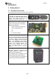
swru266 4 Getting Started 4.1 Development Kit Content The development kit includes the following main components: RF remote control A complete cost optimized RF4CE remote control reference design with integrated PCB antenna. The remote control can be programmed using the debug interface. Target Module Interface board for connecting I/O signals to typical remote applications.
swru266 USB dongle The USB dongle can be programmed to replace the functions of the Target Module. It supports virtual serial port interface and HID (Human Interface Device) USB profiles. It can also be programmed to be used as packet sniffer of RF activity. In addition the kit includes the following accessories: 2 AA batteries 2 Mini-USB cables, one for the target module and one for the CC Debugger 1 USB extension cable for the USB dongle 1 10-pin flat cable with 2x5 2.
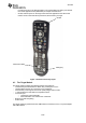
swru266 - for instructions to run the PER and latency test, and the RemoTI Latency and Packet Error Rate Application Note (SWRA262) for sample measurements. On/Off, switches power on the target. Note that most applications can still receive remote control commands when powered off, but the latency is longer On/Off Packet Error Rate Pairing key Figure 1: Remote Control Key layout 4.
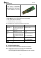
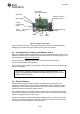
swru266 EM module, RF reference design IR receiver Interface connector SPI/UART/I2C/IR IR transmitter Current measurement jumper USB Power/interface Debug/programming interface Reset User LEDs User button Figure 2: Target module layout Figure 2 shows the key layout of the target module with some of the peripheral interfaces highlighted. For details of the target module features, please see chapter 6. 4.
swru266 The latest version of RemoTI software can be downloaded from the Texas Instruments website (http://www.ti.com/remoti), where you will also find a complete user manual. 4.6 Installing the target module Windows drivers Before your PC can communicate with the target modules over USB, you will need to install the driver files for the target module.
swru266 Figure 4: Connecting the target module for the first time (Windows XP) Select “No, not this time” and continue with “Next”. Figure 5: Select automatic installation of software (Windows XP) Select “Install from a list or specific location (Advanced)” to install the driver.
swru266 Figure 6: The driver installation is completed (Windows XP) Select the following directory \Tools\Driver for the needed *.inf and *.sys driver files. The driver is now installed and the PC is can communicate with target module using a virtual COM port. Unfortunately Windows does not confirm what COM port the device is assigned to.
swru266 4.7 Testing the Remote Control application You are now ready to use the development kit to test remote control. The RemoTI software package includes a remote control target emulator. This is an application that is running on a PC and emulates TV or A/V equipment. It controls the RemoTI receiver using a serial port interface. For real applications the target emulator SW will be running on the host processor of the equipment.
swru266 5 Programming and Debugging 5.1 Using the SmartRF Flash Programmer PC software The SmartRF Flash programmer PC software is used for programming the software on the remote control and the target module. The RemoTI installation package includes two hex files in the \RemoTI\bin folder: Remote control: Target module: rsa_CC2533.hex rnp_CC2533.hex Remote Sample Application Remote Network Processor Figure 8: SmartRF flash programmer interface 5.
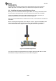
swru266 Note Pin 1 marking ● Note Pin 1 marking ► Figure 9: Connecting the remote control to the CC Debugger Care should be taken when connecting the CC Debugger cable to the remote control. There is no protection from connecting the cable with wrong orientation. The pin 1 marking on the CC Debugger adapter board must match the pin 1 marking on the remote control. On the CC Debugger adapter board pin 1 is marked with a triangle and 1 close to the connector.
swru266 Figure 10: Connecting the target module to the CC Debugger 16/25
swru266 6 The Target Module The target module is designed to allow flexible interfaces for many common types of interfaces used in typical remote control applications. The target module uses a CC2533EM RF reference design 6.1 Target module hardware description 6.1.
swru266 6.1.2 USB The USB port is used for powering the board and for serial interface to the CC2533. A TUSB3410 is used to translate the serial port interface to USB interface. Future versions of the target module may use devices with integrated USB interfaces. In order to support devices with integrated USB interface 0-ohm resistors are used to select between interfacing USB directly to TUSB3410 and to the EM connector. Figure 11: USB interface selection with 0-ohm resistor 6.1.
swru266 UART CTS(P1.3) 5 6 UART RTS(P2.18) SPI CSN(P1.14) 7 8 SCLK(P1.16) MOSI(P1.18) 9 10 MISO(P1.20) I2C SDA(P1.11) 11 12 I2C SCL(P1.5) EM_RESET((P2.15) 13 14 IR_OUT1(P1.13) Table 2: Interface header pinout 6.1.5 Debug interface A 2x5 pin 1.27 mm pitch header (J5) is used for programming and debugging the CC2533 on the EM socket. The pinout of this connector is shown in Table 3 below. EM connector pin numbers in parentheses.
swru266 The IR receiver is a Vishay TSOP85238. The receiver is optimized for 38 KHz input signal. The IR input is connected to the IR_IN signal The IR transmitter is a Vishay TSKS5400S. The diode is only used for short distance IR signals as the target module is intended to be mounted on the receiver side of the equipment. The IR diode is controlled by the IR_OUT1 signals. The IR_OUT1 signal is accessible on pin 12 of the interface header connector to allow driving external signals with the IR output. 6.1.
swru266 7 Appendix A: Opening the remote control Yes, we know you will do it… Here are the instructions how to open the remote control without breaking it. First insert two thin flat screwdrivers on the bottom of the remote between the two slots. Press carefully to open the casing on the bottom.
swru266 8 Appendix B: How to upgrade the target module USB driver The target module USB driver information is stored an EEPROM for the TUSB3410 USB interface device. This EEPROM includes Vendor ID, USB ID, USB device name, and serial number. The EEPROM can be customized by programming the EEPROM via the USB interface. To modify the EEPROM content, download the EEPROM burner SW: http://www.ti.com/lit/zip/sllc259.
swru266 Remove the short on the pins 1(GND) and pin 11(I2C SDA) on the interface header before clicking “Program EEPROM” Figure 18: Using the EEPROM burner software After successful programming, unplug the mini-USB cable, mount the CC2533EM on the target module and plug in the mini-USB cable again. The target module will now appear as a COM port in the device manager.
swru266 9 Schematic and Layout The complete design files including schematic and layout for the remote control, target module, and EM module can be downloaded from http://www.ti.
swru266 10 Document History Revision Date - 2010-08-16 Description/Changes First revision.
IMPORTANT NOTICE Texas Instruments Incorporated and its subsidiaries (TI) reserve the right to make corrections, modifications, enhancements, improvements, and other changes to its products and services at any time and to discontinue any product or service without notice. Customers should obtain the latest relevant information before placing orders and should verify that such information is current and complete.