EVM User’s Guide CC3100MOD Boosterpack™ (Evaluation board) User Guide ECS Applications Table 1.
EVM User’s Guide Contents Getting Started ..........................................................................................................................4 1 Introduction .......................................................................................................................4 1.1 CC3100MOD BOOST 4 1.2 CC3100MOD Module 4 2 Hardware description ........................................................................................................5 2.1 Block Diagram 6 2.
EVM User’s Guide Getting Started 1 Introduction 1.1 CC3100MOD BOOST Introducing the CC3100MOD Booster pack compatible with all TI Launchpads for adding WIFI capability to embedded systems. The CC3100MODBOOST Booster Pack is an easy-to-use evaluation module for the CC3100 WIFI device. It contains everything needed to start developing a WIFI solution on TI Launchpad.
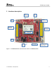
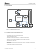
EVM User’s Guide 2 Hardware description Chip Antenna U.FL Conn nRESET (Optional) OOB 20 pin LP Connector CC3100 20 pin LP Connector CC3100MOD nHIB PWR SEL 3.
EVM User’s Guide 2.1 Block Diagram Chip Antenna U.FL Conn LED Indicators CC3100MOD SPI/UART/GPIO Push Buttons 2x20 headers Murata Conn Vcc Current Meas J8 5V J6 Jumper 3.3V 3.3V LDO Diode Mux 5V Micro USB Figure 2 : CC3100MODBOOST Block diagram 2.2 Hardware Features of the evaluation board •CC3100MOD module with fully integrated solution. 2x20 pin stackable connectors •On-board chip antenna with option for U.FL based conducted testing. •Power from on-board LDO using USB OR 3.
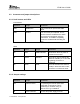
EVM User’s Guide 2.3 Connector and jumper descriptions 2.3.1 Push buttons and LEDs Push buttons Reference Usage Comments SW1 OOB Demo This is used as an input for the OOB demo. SW2 RESET The use of this pin is optional. This is used to reset the CC3100 device which can also be accomplished using the nHIB button. The RESET completely erases the CC3100 RAM including the time. LEDs Reference Colour Usage Comments D5 RED PWR Indication Glows when the 3.
EVM User’s Guide Lauchpad or the on-board USB. J8 (1-2) power from MCU Launchpad J8 (2-3) power from on-board USB using 3.3V LDO J6 Current measurement For Hibernate and LPDS currents connect a ammeter across J26 : Range (< 500uA) For Active current, mount a 0.1 Ohm resistor on R42 and measure the voltage across the 0.1 Ohm resistor using a voltmeter. Range (< 50mV peak-peak) J5 OOB Demo Closed : GPIO_12 is hard pulled to Vcc Open : GPIO_12 is pulled to GND using 33K resistor.
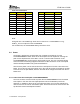
EVM User’s Guide 2.3.3 2x20 pin connector assignment The signal assignment on the 2x20 pin connector is shown below. The convention of J1..J4 is replaced with P1…P4 to avoid confusion with the actual board reference. P1 P3 P4 P2 P1 P3 P4 P2 VCC(3.
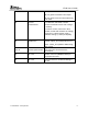
EVM User’s Guide Inner row connectors Pin No Signal Name Direction Pin No Signal Name Direction P3.1 +5V IN P4.1 UN-USED OUT P3.2 GND IN P4.2 UN-USED OUT P3.3 UN-USED NA P4.3 UN-USED NA P3.4 UN-USED NA P4.4 UART1_CTS IN P3.5 UN-USED NA P4.5 UART1_RTS OUT P3.6 UN-USED NA P4.6 UN-USED NA P3.7 UN-USED NA P4.7 NWP_LOG_TX OUT P3.8 UN-USED NA P4.8 WLAN_LOG_TX OUT P3.9 UN-USED NA P4.9 UN-USED IN P3.10 UN-USED NA P4.
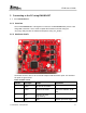
EVM User’s Guide 3 Connecting to the PC using EMUBOOST 3.1 CC31XXEMUBOOST 3.1.1 Overview The CC31XXEMUBOOST is designed to connect the CC3100MODBOOST pack to a PC using USB connection. This is used to update the firmware on the BP using the “SL_Prog” utility and also in software development using “SL_Studio”. 3.1.2 Hardware details The board has two FTDI ICs to enumerate multiple COM and D2XX ports.
EVM User’s Guide output. TX only Note : On the PC only two of the four ports would be visible on the Device Manager. The D2XX ports are not listed under the “Ports” tab. The first COM port in the list usually is used for the flash programming. Ports available on J5 Port No Port Type Usage Comments 1 VCP RT3 Used for TI internal debug only. 2 VCP MAC logger MAC logger output. TX only 3.1.3 Driver requirements The FTDI Debug board requires the user to install the associated drivers on a PC.
EVM User’s Guide 2 J22 (short) Provide 5.0V to the Booster pack 3 J3 (1-2) Route the NWP logs to the Dual port also The rest of the jumpers can remain open.
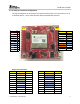
EVM User’s Guide 4 Connecting to a Launchpad The CC3100MOD Booster pack can be directly connected to a compatible Launchpad using the standard 2x20 pin connectors. The jumper settings needed for this connection is the same as that needed for the EMUBOOST board as described in the previous section. Please ensure that the Pin1 of the 2x20 pins are aligned correctly before mating. The mated setup is as per the picture below. (Note the USB cable is connected to the Booster Pack directly to power it only.
EVM User’s Guide 5 PCB information 5.
EVM User’s Guide Figure 4 : Layer-2 TI Confidential – Strictly Private 16
EVM User’s Guide 5.2 Antenna pattern The antenna used on the evaluation platform is a chip antenna from Taiyo Yuden (AH316M245001-T). The below figures depict the radiation patter from this chip antenna. Note that the radiation pattern is influenced by presence of any metal parts nearby.
EVM User’s Guide 5.
EVM User’s Guide TI Confidential – Strictly Private 19
EVM User’s Guide 5.4 Bill of materials Qty Description 2 CAP CER 100nF 10% 10V SMD 0402 GP/HF X5R 0.5mm 14 RES C SMD 0402 0ohm 5% GP/HF Part Reference PCB Footprint Part Number Manufacturer Mfr. PN C-0402S0 202.00008.015 Murata GRM155R61A104KA01D C15 C27 C-0402S0 251.00681.025 Yageo RC0402JR-070RL R15 R22 R29 R36 R37 R38 R44 R46 R48 R65 R66 R73 R81 R82 1 RES C SMD 0402 100ohm 5% GP/HF R-0402S0 251.00004.
EVM User’s Guide STANDARD TERMS AND CONDITIONS FOR EVALUATION MODULES 1. Delivery: TI delivers TI evaluation boards, kits, or modules, including any accompanying demonstration software, components, or documentation (collectively, an “EVM” or “EVMs”) to the User (“User”) in accordance with the terms and conditions set forth herein. Acceptance of the EVM is expressly subject to the following terms and conditions 1.
EVM User’s Guide 3.2 Canada 3.2.1 For EVMs issued with an Industry Canada Certificate of Conformance to RSS-210 Concerning EVMs Including Radio Transmitters: This device complies with Industry Canada license-exempt RSS standard(s). Operation is subject to the following two conditions: (1) this device may not cause interference, and (2) this device must accept any interference, including interference that may cause undesired operation of the device.
EVM User’s Guide or using the EVM, including without limitation any warning or restriction notices. The notices contain important safety information related to, for example, temperatures and voltages. 4.3 Safety-Related Warnings and Restrictions: 4.3.1 User shall operate the EVM within TI’s recommended specifications and environmental considerations stated in the user guide, other available documentation provided by TI, and any other applicable requirements and employ reasonable and customary safeguards.
EVM User’s Guide PROVIDED HEREUNDER, EXCEED THE TOTAL AMOUNT PAID TO TI FOR THE PARTICULAR UNITS SOLD UNDER THESE TERMS AND CONDITIONS WITH RESPECT TO WHICH LOSSES OR DAMAGES ARE CLAIMED. THE EXISTENCE OF MORE THAN ONE CLAIM AGAINST THE PARTICULAR UNITS SOLD TO USER UNDER THESE TERMS AND CONDITIONS SHALL NOT ENLARGE OR EXTEND THIS LIMIT. 9. Return Policy. Except as otherwise provided, TI does not offer any refunds, returns, or exchanges.