
Data Sheet
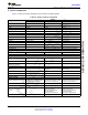
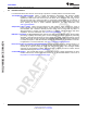
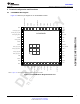
Table Of Contents
- 1 Module Overview
- Table of Contents
- 2 Revision History
- 3 Device Comparison
- 4 Terminal Configuration and Functions
- 5 Specifications
- 5.1 Absolute Maximum Ratings
- 5.2 ESD Ratings
- 5.3 Recommended Operating Conditions
- 5.4 Current Consumption Summary: 2.4 GHz RF Band
- 5.5 Current Consumption Summary: 5 GHz RF Band
- 5.6 TX Power Control for 2.4 GHz Band
- 5.7 TX Power Control for 5 GHz Band
- 5.8 Brownout and Blackout Conditions
- 5.9 Electrical Characteristics for DIO Pins
- 5.10 WLAN Receiver Characteristics
- 5.11 WLAN Transmitter Characteristics
- 5.12 BLE and WLAN Coexistence Requirements
- 5.13 Reset Requirement
- 5.14 Thermal Resistance Characteristics for MOB Package
- 5.15 Timing and Switching Characteristics
- 5.16 External Interfaces
- 6 Detailed Description
- 7 Applications, Implementation, and Layout
- 8 Environmental Requirements and SMT Specifications
- 9 Device and Documentation Support
- 10 Mechanical, Packaging, and Orderable Information
- Important Notice

TI Confidential – NDA Restrictions
ADVANCEINFORMATION
10
CC3135MOD
SWRS225A –FEBRUARY 2019–REVISED AUGUST 2019
www.ti.com
Submit Documentation Feedback
Product Folder Links: CC3135MOD
Terminal Configuration and Functions Copyright © 2019, Texas Instruments Incorporated
4.2 Pin Attributes
Table 4-1 describes the CC3135MOD pins.
NOTE
Digital IOs on the CC3135MOD refer to hostless mode, BLE/2.4 GHz coexistence, and
antenna select IOs, not general-purpose IOs.
If an external device drives a positive voltage to signal pads when the CC3135MOD is not
powered, DC current is drawn from the other device. If the drive strength of the external
device is adequate, an unintentional wakeup and boot of the CC3135MOD device can occur.
To prevent current draw, TI recommends one of the following:
• All devices interfaced to the CC3135MOD must be powered from the same power rail as
the CC3135MOD device.
• Use level shifters between the CC3135MOD and any external devices fed from other
independent rails.
• The nRESET pin of the CC3135MOD device must be held low until the V
BAT
supply to
the device is driven and stable.