
Data Sheet
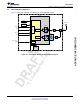
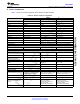
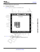
Table Of Contents
- 1 Module Overview
- Table of Contents
- 2 Revision History
- 3 Device Comparison
- 4 Terminal Configuration and Functions
- 5 Specifications
- 5.1 Absolute Maximum Ratings
- 5.2 ESD Ratings
- 5.3 Recommended Operating Conditions
- 5.4 Current Consumption Summary: 2.4 GHz RF Band
- 5.5 Current Consumption Summary: 5 GHz RF Band
- 5.6 TX Power Control for 2.4 GHz Band
- 5.7 TX Power Control for 5 GHz Band
- 5.8 Brownout and Blackout Conditions
- 5.9 Electrical Characteristics for DIO Pins
- 5.10 WLAN Receiver Characteristics
- 5.11 WLAN Transmitter Characteristics
- 5.12 BLE and WLAN Coexistence Requirements
- 5.13 Reset Requirement
- 5.14 Thermal Resistance Characteristics for MOB Package
- 5.15 Timing and Switching Characteristics
- 5.16 External Interfaces
- 6 Detailed Description
- 7 Applications, Implementation, and Layout
- 8 Environmental Requirements and SMT Specifications
- 9 Device and Documentation Support
- 10 Mechanical, Packaging, and Orderable Information
- Important Notice

TI Confidential – NDA Restrictions
ADVANCEINFORMATION
6
CC3135MOD
SWRS225A –FEBRUARY 2019–REVISED AUGUST 2019
www.ti.com
Submit Documentation Feedback
Product Folder Links: CC3135MOD
Revision History Copyright © 2019, Texas Instruments Incorporated
2 Revision History
Changes from Original (February 2019) to Revision A Page
• Changed Figure 1-1 .................................................................................................................. 3
• Deleted footnote from Table 5-5 .................................................................................................. 25
• Changed MIC ID in Table 6-3 ..................................................................................................... 42
• Changed Section 8.1.1 ............................................................................................................. 56
• Changed shelf life in Section 8.3.1................................................................................................ 56
• Changed assembly operations in Section 8.4.2 ................................................................................ 56
• Changed solder paste composition in Section 8.6.............................................................................. 58
• Changed peak temperature in Section 8.6....................................................................................... 58
• Changed Figure 8-1 ................................................................................................................ 58
• Added Table 8-1 .................................................................................................................... 58
• Changed Figure 9-1 ................................................................................................................ 59
• Changed first NOTE in Section 10.1 ............................................................................................. 62