
Datasheet


1
Data sheet acquired from Harris Semiconductor
SCHS141H
Features
• Hysteresis on Clock Inputs for Improved Noise
Immunity and Increased Input Rise and Fall Times
• Asynchronous Set and Reset
• Complementary Outputs
• Buffered Inputs
• Typical f
MAX
= 60MHz at V
CC
= 5V, C
L
= 15pF,
T
A
= 25
o
C
• Fanout (Over Temperature Range)
- Standard Outputs. . . . . . . . . . . . . . . 10 LSTTL Loads
- Bus Driver Outputs . . . . . . . . . . . . . 15 LSTTL Loads
• Wide Operating Temperature Range . . . -55
o
C to 125
o
C
• Balanced Propagation Delay and Transition Times
• Significant Power Reduction Compared to LSTTL
Logic ICs
• HC Types
- 2V to 6V Operation
- High Noise Immunity: N
IL
= 30%, N
IH
= 30% of V
CC
at V
CC
= 5V
• HCT Types
- 4.5V to 5.5V Operation
- Direct LSTTL Input Logic Compatibility,
V
IL
= 0.8V (Max), V
IH
= 2V (Min)
- CMOS Input Compatibility, I
l
≤ 1µA at V
OL
, V
OH
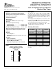
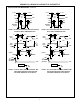
Pinout
CD54HC112, CD54HCT112 (CERDIP)
CD74HC112 (PDIP, SOIC, SOP, TSSOP)
CD74HCT112 (PDIP)
TOP VIEW
Description
The ’HC112 and ’HCT112 utilize silicon-gate CMOS
technology to achieve operating speeds equivalent to LSTTL
parts. They exhibit the low power consumption of standard
CMOS integrated circuits, together with the ability to drive 10
LSTTL loads.
These flip-flops have independent J, K, Set, Reset, and
Clock inputs and Q and
Q outputs. They change state on the
negative-going transition of the clock pulse. Set and Reset
are accomplished asynchronously by low-level inputs.
The HCT logic family is functionally as well as pin-
compatible with the standard LS logic family.
.
14
15
16
9
13
12
11
10
1
2
3
4
5
7
6
8
1CP
1K
1J
1S
1Q
1Q
GND
2Q
V
CC
2R
2CP
2K
2J
2S
2Q
1R
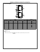
Ordering Information
PART NUMBER
TEMP. RANGE
(
o
C) PACKAGE
CD54HC112F3A -55 to 125 16 Ld CERDIP
CD54HCT112F3A -55 to 125 16 Ld CERDIP
CD74HC112E -55 to 125 16 Ld PDIP
CD74HC112MT -55 to 125 16 Ld SOIC
CD74HC112M96 -55 to 125 16 Ld SOIC
CD74HC112NSR -55 to 125 16 Ld SOP
CD74HC112PW -55 to 125 16 Ld TSSOP
CD74HC112PWR -55 to 125 16 Ld TSSOP
CD74HC112PWT -55 to 125 16 Ld TSSOP
CD74HCT112E -55 to 125 16 Ld PDIP
NOTE: When ordering, use the entire part number. The suffixes 96
and R denote tape and reel. The suffix T denotes a small-quantity
reel of 250.
CAUTION: These devices are sensitive to electrostatic discharge. Users should follow proper IC Handling Procedures.
Copyright
© 2003, Texas Instruments Incorporated
CD54HC112, CD74HC112,
CD54HCT112, CD74HCT112
Dual J-K Flip-Flop with Set and Reset
Negative-Edge Trigger
[
/Title
(
CD74
H
C112
,
C
D74
H
CT11
2
)
/
Sub-
j
ect
(
Dual
J
-K
F
lip-
F
lop
w
ith
S
etand
R
eset
N
ega-
March 1998 - Revised October 2003