
User manual

Timer_A Operation
12-10 Timer_A
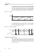
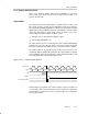
Changing the Period Register TACCR0
When changing TACCR0 while the timer is running, and counting in the down
direction, the timer continues its descent until it reaches zero. The new period
takes affect after the counter counts down to zero.
When the timer is counting in the up direction, and the new period is greater
than or equal to the old period, or greater than the current count value, the timer
counts up to the new period before counting down. When the timer is counting
in the up direction, and the new period is less than the current count value, the
timer begins counting down. However, one additional count may occur before
the counter begins counting down.
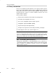
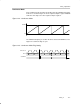
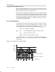
Use of the Up/Down Mode
The up/down mode supports applications that require dead times between
output signals (See section Timer_A Output Unit). For example, to avoid
overload conditions, two outputs driving an H-bridge must never be in a high
state simultaneously. In the example shown in Figure 12−9 the t
dead
is:
t
dead
= t
timer
× (TACCR1 − TACCR2)
With: t
dead
Time during which both outputs need to be inactive
t
timer
Cycle time of the timer clock
TACCRx Content of capture/compare register x
The TACCRx registers are not buffered. They update immediately when
written to. Therefore, any required dead time will not be maintained
automatically.
Figure 12−9. Output Unit in Up/Down Mode
0h
0FFFFh
TAIFG
Output Mode 2: Toggle/Reset
Output Mode 6: Toggle/Set
TACCR0
TACCR1
EQU1
TAIFG
Interrupt Events
EQU1
EQU0
EQU1 EQU1
EQU0
TACCR2
EQU2 EQU2EQU2 EQU2
Dead Time