
User manual

Timer_A Operation
12-15Timer_A
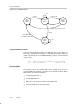
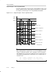
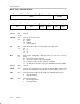
Output Example—Timer in Continuous Mode
The OUTx signal is changed when the timer reaches the TACCRx and
TACCR0 values, depending on the output mode. An example is shown in
Figure 12−13 using TACCR0 and TACCR1.
Figure 12−13. Output Example—Timer in Continuous Mode
0h
0FFFFh
TAIFG
Output Mode 1: Set
Output Mode 2: Toggle/Reset
Output Mode 3: Set/Reset
Output Mode 4: Toggle
Output Mode 5: Reset
Output Mode 6: Toggle/Set
Output Mode 7: Reset/Set
TACCR0
TACCR1
EQU1 TAIFG EQU1 EQU0 Interrupt EventsEQU0