
User manual

Comparator_A Operation
17-4 Comparator_A
17.2 Comparator_A Operation
The comparator_A module is configured with user software. The setup and
operation of comparator_A is discussed in the following sections.
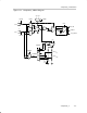
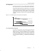
17.2.1 Comparator
The comparator compares the analog voltages at the + and – input terminals.
If the + terminal is more positive than the – terminal, the comparator output
CAOUT is high. The comparator can be switched on or off using control bit
CAON. The comparator should be switched off when not in use to reduce
current consumption. When the comparator is switched off, the CAOUT is
always low.
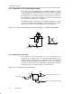
17.2.2 Input Analog Switches
The analog input switches connect or disconnect the two comparator input
terminals to associated port pins using the P2CAx bits. Both comparator
terminal inputs can be controlled individually. The P2CAx bits allow:
- Application of an external signal to the + and – terminals of the comparator
- Routing of an internal reference voltage to an associated output port pin
Internally, the input switch is constructed as a T-switch to suppress distortion
in the signal path.
Note: Comparator Input Connection
When the comparator is on, the input terminals should be connected to a
signal, power, or ground. Otherwise, floating levels may cause unexpected
interrupts and increased current consumption.
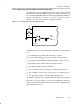
The CAEX bit controls the input multiplexer, exchanging which input signals
are connected to the comparator’s + and – terminals. Additionally, when the
comparator terminals are exchanged, the output signal from the comparator
is inverted. This allows the user to determine or compensate for the
comparator input offset voltage.