
User manual


LCD Controller Operation
18-13LCD Controller
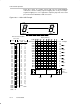
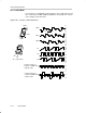
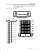
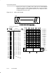
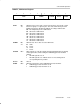
Figure 18−8 shows an example 3-mux LCD, pin-out, LCD-to-MSP430
connections, and the resulting segment mapping. This is only an example.
Segment mapping in a user’s application depends on the LCD pin-out and on
the MSP430-to-LCD connections.
Figure 18−8. 3-Mux LCD Example
28
e
h
d
A
B
G
0
3
A
B
G
0
3
3 210 0
gd e
32103210
Sn+1 Sn
Parallel-
Serial
Conversion
COM
a
b
c
d
e
f
g
h
a
b
c
d
e
f
g
h
a-- fy--
fe hy-- cb--
ch db-- ga--
gd ea-- fy--
fe hy-- cb--
ch db-- ga--
gd ea-- fy--
fe hy-- cb--
ch db-- ga--
gd ea-- fy--
fe hy-- cb--
ch db-- ga--
gda-- fy--
fey-- cb--
chb-- ga--
26
24
22
20
18
16
14
12
10
8
6
4
2
0
Digit 9
Digit 7
Digit 4
Digit 2
3 21
y y
Digit 5
Digit 3
Digit 1
Digit 6
Digit 8
Digit 10
DIGIT10 DIGIT1
S0
S1
S2
S3
S4
S5
S6
S7
S8
S9
S10
S11
S12
S13
S14
S15
S16
S17
S18
S19
S20
S21
S22
S23
S24
S25
S26
S27
S28
S29
COM0
COM1
COM2
COM3
1
2
3
4
5
6
7
8
9
10
11
12
13
14
15
16
17
18
19
20
21
22
23
24
25
26
27
28
29
30
31
32
33
1e
1d
1h
2e
2d
2h
3e
3d
3h
4e
4d
4h
5e
5d
5h
6e
6d
6h
7e
7d
7h
8e
8d
8h
9e
9d
9h
10e
10d
10h
COM0
PIN COM0
’430 Pins LCD Pinout
Pinout and Connections
NC
1f
1g
1c
2f
2g
2c
3f
3g
3c
4f
4g
4c
5f
5g
5c
6f
6g
6c
7f
7g
7c
8f
8g
8c
9f
9g
9c
10f
10g
10c
COM1
COM1
1y
1a
1b
2y
2a
2b
3y
3a
3b
4y
4a
4b
5y
5a
5b
6y
6a
6b
7y
7a
7b
8y
8a
8b
9y
9a
9b
10y
10a
10b
COM2
COM2
Display Memory
LCD
Connections
egda-- fy--
091h
092h
093h
094h
095h
096h
097h
098h
099h
09Ah
09Bh
09Ch
09Dh
09Eh
09Fh
MAB
n = 30