
User manual

LCD_A Controller Operation
19-18 LCD_A Controller
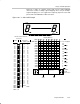
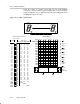
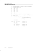
19.2.9 4-Mux Mode
In 3-mux mode, each MSP430 segment pin drives four LCD segments and all
four common lines, COM0, COM1, COM2, and COM3 are used. Figure 19−10
shows some example 4-mux, 1/3 bias waveforms.
Figure 19−10. Example 4-Mux Waveforms
f
frame
V1
V2
V4
V5
V1
0 V
−V1
V1
0 V
−V1
COM0
COM1
COM2
COM3
SP1
SP2
COM3
COM2
COM1
COM0
SP2
SP1
Resulting Voltage for
Segment e (COM1−SP1)
Segment Is Off.
Resulting Voltage for
Segment c (COM1−SP2)
Segment Is On.
SP = Segment Pin
c
e
V1
V2
V4
V5
V1
V2
V4
V5
V1
V2
V4
V5
V1
V2
V4
V5
V1
V2
V4
V5