
User manual

ADC12 Operation
20-7ADC12
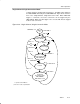
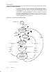
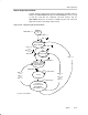
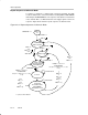
20.2.5 Sample and Conversion Timing
An analog-to-digital conversion is initiated with a rising edge of the sample
input signal SHI. The source for SHI is selected with the SHSx bits and
includes the following:
- The ADC12SC bit
- The Timer_A Output Unit 1
- The Timer_B Output Unit 0
- The Timer_B Output Unit 1
The polarity of the SHI signal source can be inverted with the ISSH bit. The
SAMPCON signal controls the sample period and start of conversion. When
SAMPCON is high, sampling is active. The high-to-low SAMPCON transition
starts the analog-to-digital conversion, which requires 13 ADC12CLK cycles.
Two different sample-timing methods are defined by control bit SHP, extended
sample mode and pulse mode.
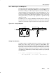
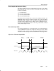
Extended Sample Mode
The extended sample mode is selected when SHP = 0. The SHI signal directly
controls SAMPCON and defines the length of the sample period t
sample.
When
SAMPCON is high, sampling is active. The high-to-low SAMPCON transition
starts the conversion after synchronization with ADC12CLK. See Figure 20−3.
Figure 20−3. Extended Sample Mode
Start
Sampling
Stop
Sampling
Conversion
Complete
SAMPCON
SHI
t
sample
t
convert
t
sync
13 x ADC12CLK
Start
Conversion
ADC12CLK