
User manual

SD16_A Operation
22-6 SD16_A
22.2.7 Digital Filter
The digital filter processes the 1-bit data stream from the modulator using a
SINC
3
comb filter. The transfer function is described in the z-Domain by:
H
(
z
)
+
ǒ
1
OSR
1 * z
*OSR
1 * z
*1
Ǔ
3
and in the frequency domain by:
H
ǒ
f
Ǔ
+
ȧ
ȱ
Ȳ
sinc
ǒ
OSRp
f
f
M
Ǔ
sinc
ǒ
p
f
f
M
Ǔ
ȧ
ȳ
ȴ
3
+
ȧ
ȡ
Ȣ
1
OSR
sin
ǒ
OSR p
f
f
M
Ă
Ǔ
sin
ǒ
p
f
f
M
Ă
Ǔ
ȧ
ȣ
Ȥ
3
where the oversampling rate, OSR, is the ratio of the modulator frequency f
M
to the sample frequency f
S
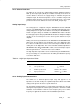
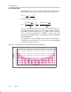
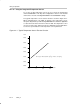
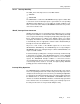
. Figure 22−2 shows the filter’s frequency response
for an OSR of 32. The first filter notch is at f
S
= f
M
/OSR. The notch’s frequency
can be adjusted by changing the modulator’s frequency, f
M
, using
SD16SSELx and SD16DIVx and the oversampling rate using the SD16OSRx
and SD16XOSR bits .
The digital filter for each enabled ADC channel completes the decimation of
the digital bit-stream and outputs new conversion results to the SD16MEM0
register at the sample frequency f
S
.
Figure 22−2. Comb Filter’s Frequency Response with OSR = 32
−140
−120
−100
−80
−60
−40
−20
0
Frequency
GAIN [dB]
f
S
f
M