
User manual

Scan IF Operation
24-21Scan IF
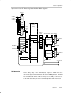
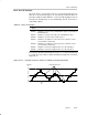
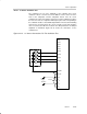
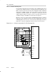
Figure 24−11.Scan IF Processing State Machine Block Diagram
Q0
Q3
Q4
Q5
Q6
Q7
S2
S1
SIFQ6EN
SIFQ7EN
Q7 . . . Q0
Q0
Q1
Q2
Q3
Q4
Q5
Q6
Q7
MSP430
Memory
Range
State Table
SIFCNT1
+1
−1
SIFCNT1ENM
SIFEN
SIFCNT1ENP
SIFIS1x
SIFCNT2
−1
SIFCNT2EN
SIFIS2x
Q6
Q7
∆1
∆4
∆64
∆256
SIFPSMV
SIF1OUT
SIF0OUT
SIF2OUT
SIF3OUT
SIFS1x
SIFS2x
Q7
State
Latch
Output
Latch
11
10
01
00
11
10
01
00
Set_SIFIFG4
11
10
01
00
11
10
01
00
Set_SIFIFG5
Set_SIFIFG7
Set_SIFIFG3
∆1
∆4
∆64
∆256
SISTOP(tsm)
SIFCNTRST
PSM Operation
At the falling edge of the SIFSTOP(tsm) signal the PSM moves the
current-state byte from the PSM state table to the PSM output latch. The PSM
has one dedicated channel of direct memory access (DMA), so all accesses
to the PSM state table(s) are done automatically with no CPU intervention.