
User manual


9.8 Emulation Control
9.8.1 Set Emulator Suspend Source
Emulation Control
www.ti.com
Prioritization within each switched central resource (SCR) is selected to be either fixed or dynamic.
Dynamic prioritization is based on an incoming priority signal from each master. On the DM646x DMSoC,
all master peripherals are programmed in the bus master priority control registers (MSTRPRI n) in the
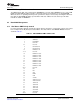
System Module. The default priority level for each bus master is listed in Table 9-2 . Application software is
expected to modify these values to obtain the desired system performance.
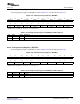
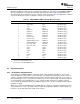
Table 9-2. TMS320DM646x DMSoC Default Master Priorities
Default Priority Level Bus Master Priority Bit Field Priority Control Register
1 VPIF Capture VP0P MSTPRI2 Register
1 VPIF Display VP1P MSTPRI2 Register
1 TSIF0 TSIF0P MSTPRI2 Register
1 TSIF1 TSIF1P MSTPRI2 Register
2 EDMA3TC0 EDMATC0P MSTPRI2 Register
(1)
2 EDMA3TC1 EDMATC1P MSTPRI2 Register
(1)
2 EDMA3TC2 EDMATC2P MSTPRI2 Register
(1)
2 EDMA3TC3 EDMATC3P MSTPRI2 Register
(1)
3 HDVICP0 (CFG) HDVICP0P MSTPRI0 Register
3 HDVICP1 (CFG) HDVICP1P MSTPRI0 Register
4 ARM926 (ARM Instruction) ARMINSTP MSTPRI0 Register
4 ARM926 (ARM Data) ARMDATAP MSTPRI0 Register
4 C64x+ DSP (DMA) DSPDMAP MSTPRI0 Register
(2)
4 C64x+ DSP (CFG) DSPCFGP MSTPRI0 Register
4 VDCE VDCEP MSTPRI1 Register
5 EMAC EMACP MSTPRI1 Register
5 USB2.0 USBP MSTPRI1 Register
5 ATA ATAP MSTPRI1 Register
5 VLYNQ VLYNQP MSTPRI1 Register
6 PCI PCIP MSTPRI1 Register
6 HPI HPIP MSTPRI1 Register
(1)
Default value in EDMA QUEPRI register
(2)
Default value in DSP MDMAARBE.PRI field
The flexibility of the DM646x DMSoC architecture allows either the ARM or the DSP to control some
various peripherals (setup registers, service interrupts, etc.). While this assignment is purely a matter of
software convention, during an emulation halt, the device must know which peripherals are associated
with the halting processor, so that only those modules receive the suspend signal. This allows peripherals
associated with the other (unhalted) processor to continue normal operation. The emulator suspend
source register (SUSPSRC) indicates the emulation suspend source for those peripherals which support
emulation suspend.
When the associated SUSPSRC bit is 0, the ARM emulator controls the peripheral’s emulation suspend
signal and when it is set to 1, the DSP emulator controls the peripheral's emulation suspend signal. See
the device-specific data manual for details on this register.
System Control Module108 SPRUEP9A – May 2008
Submit Documentation Feedback