
Datasheet

COP8SGE5, COP8SGE7, COP8SGH5
COP8SGK5, COP8SGR5, COP8SGR7
SNOS516E –JANUARY 2000–REVISED APRIL 2013
www.ti.com
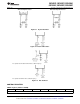
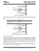
Crystal Oscillator
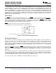
The crystal Oscillator mode can be selected by programming ECON Bit 4 to 1. CKI is the clock input while
G7/CKO is the clock generator output to the crystal. An on-chip bias resistor connected between CKI and CKO
can be enabled by programming ECON Bit 3 to 1 with the crystal oscillator option selection. The value of the
resistor is in the range of 0.5M to 2M (typically 1.0M). Table 3 shows the component values required for various
standard crystal values. Resistor R2 is only used when the on-chip bias resistor is disabled. Figure 21 shows the
crystal oscillator connection diagram.
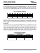
Table 3. Crystal Oscillator Configuration,
T
A
= 25°C, V
CC
= 5V
CKI Freq.
R1 (kΩ) R2 (MΩ) C1 (pF) C2 (pF)
(MHz)
0 1 18 18 15
0 1 20 20 10
0 1 25 25 4
5.6 1 100 100–156 0.455
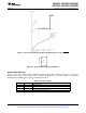
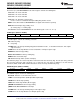
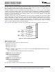
External Oscillator
The External Oscillator mode can be selected by programming ECON Bit 3 to 0 and ECON Bit 4 to 0. CKI can be
driven by an external clock signal provided it meets the specified duty cycle, rise and fall times, and input levels.
G7/CKO is available as a general purpose input G7 and/or Halt control. Figure 22 shows the external oscillator
connection diagram.
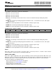
R/C Oscillator
The R/C Oscillator mode can be selected by programming ECON Bit 3 to 1 and ECON Bit 4 to 0. In R/C
oscillation mode, CKI is left floating, while G7/CKO is available as a general purpose input G7 and/or HALT
control. The R/C controlled oscillator has on-chip resistor and capacitor for maximum R/C oscillator frequency
operation. The maximum frequency is 5 MHz ± 35% for V
CC
between 4.5V to 5.5V and temperature range of
−40°C to +85°C. For max frequency operation, the CKI pin should be left floating. For lower frequencies, an
external capacitor should be connected between CKI and either V
CC
or GND. Immunity of the R/C oscillator to
external noise can be improved by connecting one half the external capacitance to V
CC
and one half to GND. PC
board trace length on the CKI pin should be kept as short as possible. Table 4 shows the oscillator frequency as
a function of external capacitance on the CKI pin. Figure 23 shows the R/C oscillator configuration.
Table 4. R/C Oscillator Configuration,
−40°C to +85°C, V
CC
= 4.5V to 5.5V,
OSC Freq. Variation of ± 35%
External Capacitor (pF)
(1)
R/C OSC Freq (MHz) Instr. Cycle (μs)
0 5 2.0
9 4 2.5
52 2 5.0
125 1 10
6100 32 kHz 312.5
(1) Assumes 3-5 pF board capacitance.
24 Submit Documentation Feedback Copyright © 2000–2013, Texas Instruments Incorporated
Product Folder Links: COP8SGE5 COP8SGE7 COP8SGH5 COP8SGK5 COP8SGR5 COP8SGR7