
Datasheet

COP8SGE5, COP8SGE7, COP8SGH5
COP8SGK5, COP8SGR5, COP8SGR7
www.ti.com
SNOS516E –JANUARY 2000–REVISED APRIL 2013
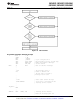
If the VIS instruction is executed, but no interrupts are enabled and pending, the lowest-priority interrupt vector is
used, and a jump is made to the corresponding address in the vector table. This is an unusual occurrence, and
may be the result of an error. It can legitimately result from a change in the enable bits or pending flags prior to
the execution of the VIS instruction, such as executing a single cycle instruction which clears an enable flag at
the same time that the pending flag is set. It can also result, however, from inadvertent execution of the VIS
command outside of the context of an interrupt.
The default VIS interrupt vector can be useful for applications in which time critical interrupts can occur during
the servicing of another interrupt. Rather than restoring the program context (A, B, X, etc.) and executing the
RETI instruction, an interrupt service routine can be terminated by returning to the VIS instruction. In this case,
interrupts will be serviced in turn until no further interrupts are pending and the default VIS routine is started.
After testing the GIE bit to ensure that execution is not erroneous, the routine should restore the program context
and execute the RETI to return to the interrupted program.
This technique can save up to fifty instruction cycles (t
c
), or more, (50µs at 10 MHz oscillator) of latency for
pending interrupts with a penalty of fewer than ten instruction cycles if no further interrupts are pending.
To ensure reliable operation, the user should always use the VIS instruction to determine the source of an
interrupt. Although it is possible to poll the pending bits to detect the source of an interrupt, this practice is not
recommended. The use of polling allows the standard arbitration ranking to be altered, but the reliability of the
interrupt system is compromised. The polling routine must individually test the enable and pending bits of each
maskable interrupt. If a Software Trap interrupt should occur, it will be serviced last, even though it should have
the highest priority. Under certain conditions, a Software Trap could be triggered but not serviced, resulting in an
inadvertent “locking out” of all maskable interrupts by the Software Trap pending flag. Problems such as this can
be avoided by using VIS instruction.
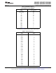
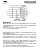
Table 7. Interrupt Vector Table
Vector Address
(1)
Arbitration Ranking Source Description
(Hi-Low Byte)
(1) Highest Software INTR Instruction 0yFE–0yFF
(2) Reserved 0yFC–0yFD
(3) External G0 0yFA–0yFB
(4) Timer T0 Underflow 0yF8–0yF9
(5) Timer T1 T1A/Underflow 0yF6–0yF7
(6) Timer T1 T1B 0yF4–0yF5
(7) MICROWIRE/PLUS BUSY Low 0yF2–0yF3
(8) Reserved 0yF0–0yF1
(9) USART Receive 0yEE–0yEF
(10) USART Transmit 0yEC–0yED
(11) Timer T2 T2A/Underflow 0yEA–0yEB
(12) Timer T2 T2B 0yE8–0yE9
(13) Timer T3 T2A/Underflow 0yE6–0yE7
(14) Timer T3 T3B 0yE4–0yE5
(15) Port L/Wakeup Port L Edge 0yE2–0yE3
(16) Lowest Default VIS Reserved 0yE0–0yE1
(1) y is a variable which represents the VIS block. VIS and the vector table must be located in the same 256-byte block except if VIS is
located at the last address of a block. In this case, the table must be in the next block.
Copyright © 2000–2013, Texas Instruments Incorporated Submit Documentation Feedback 47
Product Folder Links: COP8SGE5 COP8SGE7 COP8SGH5 COP8SGK5 COP8SGR5 COP8SGR7