
Datasheet

COP8SGE5, COP8SGE7, COP8SGH5
COP8SGK5, COP8SGR5, COP8SGR7
www.ti.com
SNOS516E –JANUARY 2000–REVISED APRIL 2013
Instruction Set
INTRODUCTION
This section defines the instruction set of the COP8 Family members. It contains information about the instruction
set features, addressing modes and types.
INSTRUCTION FEATURES
The strength of the instruction set is based on the following features:
• Mostly single-byte opcode instructions minimize program size.
• One instruction cycle for the majority of single-byte instructions to minimize program execution time.
• Many single-byte, multiple function instructions such as DRSZ.
• Three memory mapped pointers: two for register indirect addressing, and one for the software stack.
• Sixteen memory mapped registers that allow an optimized implementation of certain instructions.
• Ability to set, reset, and test any individual bit in data memory address space, including the memory-mapped
I/O ports and registers.
• Register-Indirect LOAD and EXCHANGE instructions with optional automatic post-incrementing or
decrementing of the register pointer. This allows for greater efficiency (both in cycle time and program code)
in loading, walking across and processing fields in data memory.
• Unique instructions to optimize program size and throughput efficiency. Some of these instructions are DRSZ,
IFBNE, DCOR, RETSK, VIS and RRC.
ADDRESSING MODES
The instruction set offers a variety of methods for specifying memory addresses. Each method is called an
addressing mode. These modes are classified into two categories: operand addressing modes and transfer-of-
control addressing modes. Operand addressing modes are the various methods of specifying an address for
accessing (reading or writing) data. Transfer-of-control addressing modes are used in conjunction with jump
instructions to control the execution sequence of the software program.
Operand Addressing Modes
The operand of an instruction specifies what memory location is to be affected by that instruction. Several
different operand addressing modes are available, allowing memory locations to be specified in a variety of ways.
An instruction can specify an address directly by supplying the specific address, or indirectly by specifying a
register pointer. The contents of the register (or in some cases, two registers) point to the desired memory
location. In the immediate mode, the data byte to be used is contained in the instruction itself.
Each addressing mode has its own advantages and disadvantages with respect to flexibility, execution speed,
and program compactness. Not all modes are available with all instructions. The Load (LD) instruction offers the
largest number of addressing modes.
The available addressing modes are:
• Direct
• Register B or X Indirect
• Register B or X Indirect with Post-Incrementing/Decrementing
• Immediate
• Immediate Short
• Indirect from Program Memory
The addressing modes are described below. Each description includes an example of an assembly language
instruction using the described addressing mode.
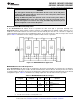
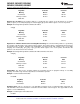
Direct. The memory address is specified directly as a byte in the instruction. In assembly language, the direct
address is written as a numerical value (or a label that has been defined elsewhere in the program as a
numerical value).
Example: Load Accumulator Memory Direct
LD A,05
Copyright © 2000–2013, Texas Instruments Incorporated Submit Documentation Feedback 59
Product Folder Links: COP8SGE5 COP8SGE7 COP8SGH5 COP8SGK5 COP8SGR5 COP8SGR7