
TV Converter Box User Manual


Basic Test Procedure
www.ti.com
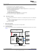
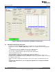
Figure 8. TSW3100 CommsSignalPattern (WCDMA) Programming GUI
3.4 DAC348x Software Quick Start Guide
• Provide the clock input 1228.8 MHz at 1.5Vrms at J9 SMA connector of the DAC3484 EVM.
• Provide the LO source of 1.9GHz (12dBm max) at either J19 or J22 SMA connector of the DAC3484
EVM.
– Provide the LO source to J24 SMA connector for the DAC3482 EVM
• Turn on power to the board and press the reset button on the EVM
• Press the “Reset USB Port” button in GUI and verify USB communication.
• Switch to the INPUT tab of GUI
• Click “LOAD REGS”, browse to the installation folder and load example file
DAC3484_FDAC_1228p8MHz_4xint_NCO_30MHz_QMCon.txt. This file contains settings for 4x
interpolation with the DAC3484 running at 1228.8MSPS. Load this file and wait a couple of seconds for
the settings to go into effect.
• Verify the spectrum using the Spectrum Analyzer at the two RF outputs of the DAC EVM (J20 and
J21).
• (Toggle the SIF SYNC button to sync the appropriate digital blocks, if example file with NCO
setting is used)
10
DAC3484/DAC3482 EVM SLAU336–March 2011
Submit Documentation Feedback
© 2011, Texas Instruments Incorporated