
Datasheet

www.ti.com
2.3 Bill of Materials
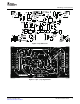
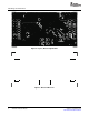
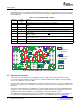
PCB Design and Performance
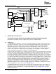
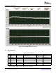
Figure 7. INL and DNL Characteristic Plot
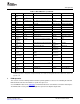
Table 1. Bill of Materials
Qty. Value Designators Description Vendor Vendor Part Number
1 N/A N/A Printed Wiring Board Texas 6488681
Instruments
0 100pF C1
(1)
0608, Ceramic, COG, 50V, 5% TDK C1608COG1H101J
3 10 μ F C2 C3 C4 1210, Ceramic, X7R, 16V TDK C3225X7R1C106Z
10 0.1 μ F C5–C11 0805, Ceramic, X7R, 50V, 10% TDK C2012X7R1H104K
C13–C15
(2)
1 1 μ F C12 1206, Ceramic, X7R, 16V, 10% TDK C3216X7R1C105K
2 10 × 2 × 0.1 J1 J2 (Top Side) 10 Pin, Dual Row, TH Header (20 Pos.) Samtec TSM-110-01-T-DV-P
SMT
(1)
Do NOT install the following: C1, R2, R3, R4, R5, R7, R8, R14 and RP1.
(2)
Default parts for the negative reference circuit: C6, C13, C15, R26, R27 and U4.
8 DAC8871 Evaluation Module SLAU233 – September 2007
Submit Documentation Feedback