DEMĆDAI3010 User’s Guide April 2003 DAV Digital Audio/Speaker SLEU036
IMPORTANT NOTICE Texas Instruments Incorporated and its subsidiaries (TI) reserve the right to make corrections, modifications, enhancements, improvements, and other changes to its products and services at any time and to discontinue any product or service without notice. Customers should obtain the latest relevant information before placing orders and should verify that such information is current and complete.
EVM IMPORTANT NOTICE Texas Instruments (TI) provides the enclosed product(s) under the following conditions: This evaluation kit being sold by TI is intended for use for ENGINEERING DEVELOPMENT OR EVALUATION PURPOSES ONLY and is not considered by TI to be fit for commercial use.
EVM WARNINGS AND RESTRICTIONS It is important to operate this EVM within the input voltage range of ±15 V and the output voltage range of ±15 V. Exceeding the specified input range may cause unexpected operation and/or irreversible damage to the EVM. If there are questions concerning the input range, please contact a TI field representative prior to connecting the input power. Applying loads outside of the specified output range may result in unintended operation and/or possible permanent damage to the EVM.
Contents Contents 1 Description . . . . . . . . . . . . . . . . . . . . . . . . . . . . . . . . . . . . . . . . . . . . . . . . . . . . . . . . . . . . . . . . . . . . . 1.1 Block Diagram . . . . . . . . . . . . . . . . . . . . . . . . . . . . . . . . . . . . . . . . . . . . . . . . . . . . . . . . . . . . . 1.2 Use of the DEM-DAI3010 . . . . . . . . . . . . . . . . . . . . . . . . . . . . . . . . . . . . . . . . . . . . . . . . . . . . 1.2.1 Initial Settings of the DEM-DAI3010 (at shipping) . . . . . . .
Contents vi
Chapter 1 Description The DEM-DAI3010 is an evaluation board for the PCM3010 (24-bit, 96-kHz ADC and 192-kHz DAC, stereo codec). This board includes not only the PCM3010 but also analog I/O terminals, analog filter circuits, and an S/PDIF digital I/O circuit that is useful for codec evaluation. S/PDIF I/O circuits consist of a 24-bit/96-kHz digital audio interface receiver (DIR1703) and a digital audio interface transmitter (DIT4096), and include optical (TOSLINK) and coaxial S/PDIF digital I/O connectors.
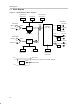
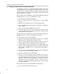
Block Diagram 1.1 Block Diagram Figure 1–1. DEM-DAI3010 Block DIagram System Clock Data Format Clock Mode X’tal Frequency System Clock SW003 SW004 JP001 DAC Output S/PDIF Input OPT. IN L-ch Output JP107 SW001 LPF PCM3010 DIR1703 R-ch Output (Slave Only) LPF COAX. IN ADC Input 24.576 MHz L-ch 1Vrms JP105 L-ch 2Vrms S/PDIF Output OPT. OUT LPF SW051 DIT4096 COAX.
Use of the DEM-DAI3010 1.2 Use of the DEM-DAI3010 The DEM-DAI3010 is shipped with standard settings preset. Therefore, connecting power supplies (15-V, –15-V and 5-V) is the only requirement to prepare the board for use, unless nonstandard settings are desired. 1.2.1 Initial Settings of the DEM-DAI3010 (at shipping) Table 1–1.
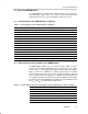
Settings and Connections for Basic Operation 1.3 Settings and Connections for Basic Operation The PCM3010 is an LSI codec containing an ADC and a DAC. Connections and settings depend on the evaluation object (ADC or DAC), and the setup should be checked carefully. Following are example settings for three typical evaluation situations. Note that when using S/PDIF I/O, the optical and coaxial input corresponds to fS = 96 kHz.
Setting Functions - Data and a clock are supplied to the PCM3010 side of JP107. - Set up FMT0 and FMT1 of SW101 according to the data format to be used. - Set up DEMP0 and DEMP1 of SW101 for the desired de-emphasis of the DAC section and PWDN for the power-down setting. 1.4 Setting Functions All functions of the devices (PCM3010, DIR1703, DIT4096) on the DEM-DAI3010 are controlled by DIP switches or header pins on this PCB.
Setting Functions 1.4.2 Detailed Explanation of Function Setting Switches and Header Pins SW001: Switch to select S/PDIF input connector (optical/coaxial). Selection of the S/PDIF signal that is routed to the DIR1703 DIN port. SW002: Reset switch for the DIR1703 and DIT4096. Pushing this switch resets the DIR1703 and DIT4096 to the initial state. A reset circuit operates at the time of power-supply connection, resetting the DIR1703 and DIT4096 automatically.
Setting Functions FMT1 FMT0 Input Data Format L L 24-bit, left-justified, MSB-first L H 24-bit, I2S (initial setting) H L 24-bit, right-justified, MSB-first H H 16-bit, right-justified, MSB-first SW006: Switch for setting channel-status data of the DIT4096. Note that the OFF state of this switch sets a HIGH level. Channel status data can set up if needed. Moreover, it is also possible to connect a microcontroller to CN002 and to write in channel-status data with the microcontroller.
Setting Functions JP001 setting table: DIR1703 system clock and crystal frequency fS in X’tal Mode 128 fS 256 fS 384 fS 512 fS BRSEL Jumper Position 32 kHz 4.096 MHz 8.192 MHz 12.288 MHz 16.384 MHz BFRAME 44.1 kHz 5.6448 MHz 11.2896 MHz 16.9344 MHz 22.5792 MHz EMFLG 48 kHz 6.144 MHz 12.288 MHz 18.432 MHz 24.576 MHz OPEN (no jumper) 88.2 kHz 11.2896 MHz 22.5792 MHz 33.8688 MHz 45.1584 MHz URBIT 96 kHz 12.288 MHz 24.576 MHz 36.864 MHz 49.
Setting Functions CN057: VCC supply selection for the PCM3010 This jumper determines whether VCC for the PCM3010 is supplied from a 3.3-V regulator on this board (U051), or via an external power supply terminal (CN056). In the initial setting, VCC is supplied from the onboard regulator. When VCC for the PCM3010 is to be provided by an external power supply, the jumper is removed from CN057 and 3.3 V is supplied to CN056. If 3.
1-10
Chapter 2 Printed-Circuit Board and Schematic This chapter presents the DEM-DAI3010 printed-circuit board and schematics. Topic Page 2.1 DEM-DAI3010 Printed-Circuit Board . . . . . . . . . . . . . . . . . . . . . . . . . . . . 2-2 2.2 DEM-DAI3010 Schematics . . . . . . . . . . . . . . . . . . . . . . . . . . . . . . . . . . . . .
DEM-DAI3010 Printed-Circuit Board 2.1 DEM-DAI3010 Printed-Circuit Board Figure 2–1.
DEM-DAI3010 Printed-Circuit Board Figure 2–2.
DEM-DAI3010 Printed-Circuit Board Figure 2–3.
DEM-DAI3010 Schematics 2.2 DEM-DAI3010 Schematics Figure 2–4. DEM-DAI3010 Analog Section R113 C119 1.2k 100pF C117 330pF R117 4.7k C121 CN101 R109 2.4k RCA pj 2 10uF /16V R111 3.3k AVCC+ JP105 1 6 8 FFC–4BMEP1 7 5 U102 4 10uF/16V OPA2134PA 2/2 C 115 1800pF 3 C123 R115 4.7k C113 10uF /16V C125 U102 10uF/16V OPA2134PA 1/2 CN103 RCA AVCC– R114 pj 1.2k C120 100pF C118 330pF R118 4.7k CN102 R110 2.4k R112 3.
DEM-DAI3010 Schematics Figure 2–5. DEM-DAI3010 Regulator, Connector and Ext.-I/F CN056 B2P–VH CN055 banana jack V DD 2 1 (Black) U051 REG1117–3.3 CN057 CN054 CN053 CN052 banana jack banana jack banana jack CN051 banana jack (Red) (Orange) (Blue) (Green) A V CC + V CC FFC–2BMEP1 2 OUT IN 3 GND C053 100uF /16V C052 10ouF /16V C051 0.1uF C055 0.
DEM-DAI3010 Schematics Figure 2–6. DEM-DAI3010 Digital Section (Digital Audio Interface) DSS108 47k x 5 RA003 2 FMT0 47k x 9 3 CLK1 CLK0 MODE MDAT MONO M/S C018 1 6 2 7 3 8 4 RA002 0.1uF 6 C015 10 uF /16V 7 47k x 3 20 8 Vcc 9 2 19 3 18 4 17 5 16 12 6 15 13 7 14 14 [TX–DATA] 8 13 9 12 [LRCK] C014 10 0.
2-8