
- TEXAS INSTRUMENTS DAV Digital Audio/Speaker User's Guide DEM-DAI3010


Settings and Connections for Basic Operation
1-4
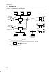
1.3 Settings and Connections for Basic Operation
The PCM3010 is an LSI codec containing an ADC and a DAC. Connections
and settings depend on the evaluation object (ADC or DAC), and the setup
should be checked carefully. Following are example settings for three typical
evaluation situations. Note that when using S/PDIF I/O, the optical and coaxial
input corresponds to f
S
= 96 kHz.
When the DAC section of PCM3010 is evaluated with S/PDIF input signal (the
PCM3010 operates as a slave of the DIR1703 PLL clock)
- Close all pins of JP107 with shorting plugs.
- Input an S/PDIF signal into the optical (U053) or coaxial (CN059)
connector.
- CN105 (L-ch) and CN106 (R-ch) are the analog signal outputs.
- Choose an S/PDIF input terminal (optical/coaxial) with the S/PDIF input
switch (SW051).
- Set the clock-mode switch (SW004) to PLL or Auto.
- The cutoff frequency of the LPF can be changed by JP101, JP102, JP103,
and JP104. All these jumpers are shorted at the time of shipment, which
sets the cutoff frequency to 20 kHz.
When the ADC section of PCM3010 is evaluated with S/PDIF output signal (the
PCM3010 operates as a slave of the DIR1703 crystal clock)
- Short all pins of JP107 with shorting plugs.
- Connect an analog signal to CN101/CN102 using an LPF, or to CN103/
CN104 using only a coupling capacitor without an LPF.
- Select the analog input terminal by changing by the settings of JP105 and
JP106. (Setup at the time of shipment is for CN101 and CN102.)
- A Toslink (U052) and a pin jack (CN058) are the S/PDIF digital output
terminals. Select the digital output connector by setting the S/PDIF output
switch (SW051). Simultaneous use of optical and coaxial outputs is
impossible.
- Set the clock mode switch (SW004) to X’tal. The X’tal mode of DIR1703
is used as a master clock for the ADC and DIT.
- Set up the channel status data using SW006.
- Because system clock frequency is 256 f
S
, the ADC section operates at
f
S
= 96 kHz. To operate the ADC section at a different f
S
, the crystal (X001)
connected to DIR1703 must be changed. The system clock setup can be
changed if required. The load capacitance used with the crystal is
dependent on the crystal properties. Therefore, when the crystal is
changed, the capacitance of C006 and C007 must be selected to match
the crystal specification.
When S/PDIF I/O is not used (the PCM3010 is evaluated alone)
- Remove all shorting plugs attached to JP107.