
- TEXAS INSTRUMENTS DAV Digital Audio/Speaker User's Guide DEM-DAI3010


Setting Functions
1-6
1.4.2 Detailed Explanation of Function Setting Switches and Header Pins
SW001: Switch to select S/PDIF input connector (optical/coaxial). Selection of the
S/PDIF signal that is routed to the DIR1703 DIN port.
SW002: Reset switch for the DIR1703 and DIT4096. Pushing this switch resets the
DIR1703 and DIT4096 to the initial state. A reset circuit operates at the time of
power-supply connection, resetting the DIR1703 and DIT4096 automatically.
Therefore, it is not usually necessary to operate this switch.
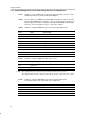
SW003: Switch for setting the DIR1703 system clock and output data format
SCF1 SCF0 System Clock
L L 128 f
S
L H 256 f
S
(initial stting)
H L 384 f
S
H H 512 f
S
FMT1 FMT0 Output Data Format
L L 16-bit right-justified, MSB-first
L H 24-bit right-justified, MSB-first
H L 24-bit left-justified, MSB-first
H H 24-bit, I
2
S (initial setting)
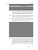
SW004: Switch for setting the DIR1703 output clock source
Position Output Clock (SCK, BCK, LRCK)
X’tal Crystal clock
PLL PLL clock
Auto PLL (PLL locked) / crystal (PLL unlocked)
Note: When using the DIR1703 as a master clock for the ADC, this switch must be set to X’tal.
When inputting S/PDIF data demodulated by the DIR1703 into the DAC, set this switch to Auto or PLL.
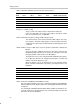
SW005: Switch for setting the DIT4096 system clock and input data format
Note that the OFF state of this switch sets a HIGH level.
CLK1 CLK0 System Clock
L L Not used
L H 256 f
S
(initial setting)
H L 384 f
S
H H 512 f
S