
- TEXAS INSTRUMENTS DAV Digital Audio/Speaker User's Guide DEM-DAI3010


Setting Functions
1-8
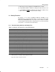
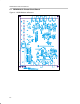
JP001 setting table: DIR1703 system clock and crystal frequency
f
S
in X’tal
Mode
128 f
S
256 f
S
384 f
S
512 f
S
BRSEL Jumper Position
32 kHz 4.096 MHz 8.192 MHz 12.288 MHz 16.384 MHz BFRAME
44.1 kHz 5.6448 MHz 11.2896 MHz 16.9344 MHz 22.5792 MHz EMFLG
48 kHz 6.144 MHz 12.288 MHz 18.432 MHz 24.576 MHz OPEN (no jumper)
88.2 kHz 11.2896 MHz 22.5792 MHz 33.8688 MHz 45.1584 MHz URBIT
96 kHz 12.288 MHz 24.576 MHz 36.864 MHz 49.152 MHz CSBIT
Sample of a of JP001 setting
Target: system clock: 256 f
S
and f
S
= 48 kHz in the X’tal mode
In the preceding table, the frequency listed where the 256-f
S
column
intersects the 48-kHz row is 12.288 MHz.
JP101–JP104: Cutoff frequency setting of DAC output post-LPF
The cutoff frequency of the LPF inserted in the DAC output is chosen by
these jumpers. The initial setting (all pins shorted) is 54 kHz at the time
of shipment. The cutoff frequency with all JP101–JP104 jumper pins open
is 108 kHz.
JP105–JP106: Selection of ADC input connectors (CN101 and CN102 or CN103 and
CN104)
There are two pairs of ADC input connectors. One pair is coupled to the
PCM3010 through capacitors (C121, C122). The other pair is connected
through a 103-kHz cutoff LPF and a –6 dB amplifier.
The input connectors are chosen by JP105 and JP106. When the jumpers
are on Direct-IN, then the left- and right-channel inputs on CN103 and
CN104, respectively, bypass the LPF.
When the jumpers are on –6 db/LPF, then the left- and right-channel
inputs on CN101 and CN102, respectively, go through the LPF to the
PCM3010.
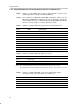
ADC Full-Scale Input Connector No. Details
L-ch 2 V rms CN101 L-ch ADC input with LPF
R-ch 2 V rms CN102 R-ch ADC input with LPF
L-ch 1 V rms CN103 L-ch ADC input without LPF
R-ch 1 V rms CN104 R-ch ADC input without LPF
JP107: Connection of PCM3010 and S/PDIF I/O circuits
This is the header pin which connects the clock input and data I/O of the PCM3010
with an S/PDIF I/O circuit. All pin positions have shorting plugs installed at the time
of shipment.
For evaluating the PCM3010 with other DSPs, DIRs, and DITs, JP107 jumpers are
removed. Connection to the alternative devices is made through the row of JP107
pins that is wired to the PCM3010.