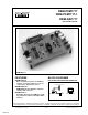
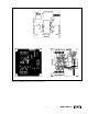
DEM-PCM1717 DEM-PCM1717-1 DEM-DAI1717 ® EVALUATION FIXTURE DEM-DAI1717 FEATURES BLOCK DIAGRAMS ● DEM-PCM1717 Basic evaluation board for the PCM1717 requires an external audio processor for connection to digital audio source. EVALUATION SOFTWARE AND CONNECTOR Centronics Connector ● DEM-PCM1717-1 DEM-PCM1717 plus Windows evaluation software and connector. ● DEM-DAI1717 Evaluation board for the PCM1717 including evaluation software and Digital Audio Interface.
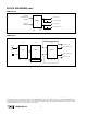
BLOCK DIAGRAMS (CONT) DEM-PCM1717 Audio Data LRCK/BCK/DATA 256/384fs Lch Direct Out Lch Capacitive Out PCM1717 Control Data ML/MC/MD Rch Direct Out Rch Capacitive Out GND +VCC DEM-DAI1717 DAI DAC LPF Lch Direct Out COAX Lch Low Pass Out SPDIF CS8412 PCM1717 OPA2604 OPT Rch Low Pass Out Rch Direct Out GND –VS +VCC GND +VS The information provided herein is believed to be reliable; however, BURR-BROWN assumes no responsibility for inaccuracies or omissions.
DEM-PCM1717 The DEM-PCM1717 is the basic evaluation fixture for the PCM1717 ∆Σ audio DAC. This fixture provides an easy way to connect power, data, and interface signals to the DAC. The hardware mode can be evaluated using this fixture by use of the on board DIP switches. These switches are connected to pins on the PCM1717 which force either power or ground to the pin. In the hardware mode some of the features of the PCM1717 can be exercised.
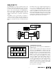
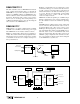
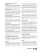
GND DIN LRCK BCK XTI CLKO CN1 CS1 CS2 S1 ML/MUTE XTAL U1 MC/DM1 MD/DM0 PCM1717E 1 + 2 C4 2.2µF 3 4 5 6 7 C6 + 10µF 8 9 10 R1 XTI DGND VDD XTO CLKO ML/MUTE LRCIN MC/DM1 DIN MC/DM0 BACKIN RSTB ZERO MODE D/C_R D/C_L VOUTR VOUTL AGND VCC C8 + 10µF RSTB MODE 20 19 18 17 ML 16 MD 15 MC C5 10µF + 14 13 RSTB 12 GND 11 + C3 2.2µF + +VCC C2 0.1µF + C1 100µF CN2 C7 10µF CN3 GND ZO VOR-C VOR-D VOL-D VOL-C FIGURE 3. DEM-PCM1717 Schematic.
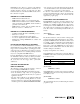
FIGURE 4. DEM-PCM1717 Parts Layout and Trace Design.
DEM-PCM1717-1 PCM1717’s special functions are programmed via a 3-wire serial interface. This type of control is commonly referred to as serial or software control. The penalty for using this mode is that the DAC must be controlled via external microprocessor or logic. But since most digital audio systems usually contain a microprocessor or micro controller, component count is not always increased.
DEM-DAI1717 also allows for operation in the hardware mode. In this mode, the special functions are limited to deemphasis frequency selection, soft mute and reset. These hardware features are controlled with DIP switches, and no PC connection is required. • Also from the previous menu the Program Group that the icon should be added to can be selected. The default choice of Applications is a good choice for this selection.
DEM-DAI1717 SYSTEM BOARD INFORMATION installed by default. An optional ground connection can be made between the receiver chip and the PCM1717E. Refer to Figure 8 for the orientation of these jumpers. GENERAL SPECIFICATIONS Table I lists the specifications for the DEM-DAI1717 system board. JP 256fs LRCK SPDIF Interface Optical via Toslink RCA with 75Ω impedance.
HARDWARE CONNECTIONS FOR THE DEM-DAI1717 software. The execute menu can be opened by either clicking on the “Execute” or by using the Alt-E key sequence. (All of the menus and commands can be activated by using the mouse and the left button or Alt key sequences). The Windows submenu (Alt-W) allows the Attenuation (Alt-A), Function (Alt-F), and Dataform (Alt-D) submenus to be opened. The function of these menus is explained in the next section.
PCM1717 FUNCTION CONTROL PCM1717E for a more detailed explanation of these formats. Selecting either of these formats is done by clicking on the Format window and selecting the desired format. This menu controls the De-emphasis, Infinite Zero Detection, and Operational Enable features of the PCM1717, as shown in Figure 18. These features are controlled by three submenus detailed below. WIDTH This menu controls the number of bits that the PCM1717 uses for digital audio conversion.
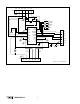
FIGURE 11. DEM-DAI1717 Schematic. 11 ® DEM-PCM1717 OPT 4 5 COAX 2 3 U4 CN3 6 TORX174 C10 0.1µF C9 10µF + 1 C11 0.047µF R1 75Ω C12 0.47µF C5 + 10µF C6 0.1µF 26 3 14 13 12 11 10 9 8 7 CS12/FCK SCK FSYNC FXN PXP DGND VD SEL M3 M2 MCK FRT AGND VA 15 16 17 18 19 20 21 22 23 24 MO M1 5 6 25 4 SDATA 27 2 CC/FO 28 U1 CS8412CP 1 C7 0.1µF C13 0.047µF R2 1kΩ C8 10µF + JP GND BCK DATA LRCK XTI S2 S1 S0 +VCC R15 C18 0.
FIGURE 12. DEM-DAI1717 Parts Layout.
FIGURE 13. DEM-DAI1717 PCB Design.
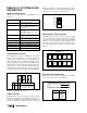
PCM1717 Control Execute (E) Execute (E) Reset (R) Window (W) Exit (X) Mode Register Register 0 01FFH Register 1 01FFH Register 2 0000H Register 3 0090H Window (W) Attenuate (A) Function (F) Dataform (D) Control Data Control Data HOLD Attenuate Level 0.00 dB Right DeEmph Format Width LRCK OFF Standard 16 bit Low = R L-Out R-Out Att Ctrl L-In R-In L<>R Mute OFF step 255 IZD OFF Output Format OPE ON 0.00 dB CLOSE CLOSE CLOSE FIGURE 14. Demo Software Main Menu.
PCM1717 Format Control Control Data PCM1717 Attenuate Control HOLD Control Data Input Format HOLD Functional Condition Format Width LRCK DeEmph Standard 16 bit Low = R OFF L-Out R-Out Att Ctrl Mute OFF L-In R-In L<>R Output Format IZD OFF CLOSE Format CLOSE Audio Data Format Select DeEmph Standard De-Emphasis Control OFF Standard OFF IIS Width OPE ON 48.0kHz 44.1kHz 32.
IMPORTANT NOTICE Texas Instruments and its subsidiaries (TI) reserve the right to make changes to their products or to discontinue any product or service without notice, and advise customers to obtain the latest version of relevant information to verify, before placing orders, that information being relied on is current and complete.