
Network Router User Manual

SM320F2812-HT
www.ti.com
SGUS062A–JUNE 2009–REVISED APRIL 2010
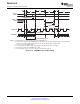
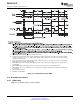
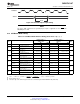
Table 6-11 is also the STANDBY Mode Wake-Up Timing Requirements table.
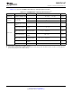
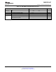
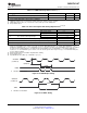
Table 6-11. STANDBY Mode Switching Characteristics
(1)
PARAMETER TEST CONDITIONS MIN TYP MAX UNIT
Delay time, IDLE instruction
t
d(IDLE-XCOH)
32 × t
c(SCO)
12 × t
c(CI)
Cycles
executed to XCLKOUT high
Without input
12 × t
c(CI)
Cycles
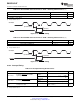
Pulse duration, external
qualifier
t
w(WAKE-INT)
wake-up signal
With input qualifier (2 + QUALSTDBY)
(2)
× t
c(CI)
Cycles
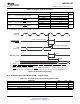
Delay time, external wake
signal to program execution
resume
(3)
–Wake-up from Flash
Without input
–Flash module in active 12 × t
c(CI)
Cycles
qualifier
state
–Wake-up from Flash
–Flash module in active With input qualifier 12 × t
c(CI)
+ t
w(WAKE-INT)
Cycles
state
t
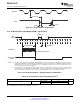
d(WAKE-STBY)
–Wake-up from Flash
Without input
–Flash module in sleep 1125 × t
c(SCO)
Cycles
qualifier
state
–Wake-up from Flash
–Flash module in sleep With input qualifier 1125 × t
c(SCO)
+ t
w(WAKE-INT)
Cycles
state
Without input
–Wake-up from SARAM 12 x tc(CI) Cycles
qualifier
–Wake-up from SARAM With input qualifier 12 × t
c(CI)
+ t
w(WAKE-INT)
Cycles
(1) Not production tested.
(2) QUALSTDBY is a 6-bit field in the LPMCR0 register.
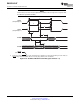
(3) This is the time taken to begin execution of the instruction that immediately follows the IDLE instruction. Execution of an ISR (triggered
by the wake-up) signal involves additional latency.
Copyright © 2009–2010, Texas Instruments Incorporated Electrical Specifications 101
Submit Documentation Feedback
Product Folder Link(s): SM320F2812-HT