
Network Router User Manual

t
su(XD)XRD
Lead
Active
Trail
DIN
t
d(XCOH-XZCSL)
t
d(XCOH-XA)
t
d(XCOHL-XRDL)
t
d(XCOHL-XZCSH)
t
d(XCOHL-XRDH)
WS (Asynch)
XCLKOUT=XTIMCLK
XCLKOUT= 1/2 XTIMCLK
XZCS0AND1
, XZCS2,
XZCS6AND7
XA[0:18]
XRD
XWE
XR/W
XD[0:15]
XREADY(Asynch)
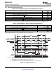
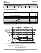
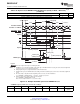
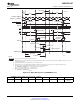
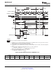
NOTES: A. All XINTF accesses (lead period) begin on the rising edge of XCLKOUT. When necessary, the device inserts an alignment cycle
before an access to meet this requirement.
B. During alignment cycles, all signals transitions to their inactive state.
C. During inactive cycles, the XINTF address bus always hold sthe last address put out on the bus. This includes alignment cycles.
D. For each sample, setup time from the beginning of the access can be calculated as:
D = (XRDLEAD + XRDACTIVE −3 +n) t
c(XTIM)
− t
su(XRDYasynchL)XCOHL
where n is the sample number: n = 1, 2, 3, and so forth.
E. Reference for the first sample is with respect to this point:
E = (XRDLEAD + XRDACTIVE −2) t
c(XTIM)
t
su(XRDYasynchL)XCOHL
t
a(XRD)
t
a(A)
t
h(XRDYasynchL)
t
h(XD)XRD
t
h(XRDYasynchH)XZCSH
= Don’t care. Signal can be high or low during this time.
Legend:
See
Note
C
t
su(XRDYasynchH)XCOHL
See
Note
D
See
Note
E
t
e(XRDYasynchH)
SM320F2812-HT
www.ti.com
SGUS062A–JUNE 2009–REVISED APRIL 2010
Figure 6-32. Example Read With Asynchronous XREADY Access
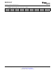
XTIMING register parameters used for this example:
XRDLEAD XRDACTIVE XRDTRAIL USEREADY X2TIMING XWRLEAD XWRACTIVE XWRTRAIL READYMODE
1 = XREADY
≥ 1 3 ≥ 1 1 0 N/A
(1)
N/A
(1)
N/A
(1)
(Asynch)
(1) N/A = "Don't care" for this example
Copyright © 2009–2010, Texas Instruments Incorporated Electrical Specifications 127
Submit Documentation Feedback
Product Folder Link(s): SM320F2812-HT