
Datasheet


DIT4096
7
SBOS225A
www.ti.com
either an input or output, and provides the frame synchroni-
zation clock for the port. The SYNC pin is also used as a data
latch clock for the channel status, user, and validity data
inputs in Hardware mode, and the user data input in Software
mode.
SLAVE OR MASTER MODE OPERATION
The audio serial port supports both Slave and Master mode
operation. In Slave mode, both SYNC and SCLK are config-
ured as inputs. The audio source device must generate both
the SYNC and SCLK clocks in Slave mode. In Master mode,
both SYNC and SCLK are configured as outputs. The audio
serial port generates the SYNC and SCLK clocks in Master
mode, deriving both from the master clock (MCLK) input.
In Software mode, Master/Slave mode selection is per-
formed using the
M/S
bit in Control Register 03
H
(defaults to
Slave mode). In Hardware mode, the
M/S
input (pin 14) is
used to select the audio serial port mode. This is shown in
Table III.
CONTROL BITS OR INPUT PIN
M/S
MASTER/SLAVE MODE SELECTION
Slave Mode; both SYNC and SCLK
are inputs.
Master Mode; both SYNC and SCLK
are outputs.
TABLE III. Master/Slave Mode Selection for Software or
Hardware Mode.
0
1
SYNC AND SCLK FREQUENCIES
The SYNC clock rate is the same as the sampling frequency,
or f
S
. This holds true for both Slave and Master modes. The
DIT4096 supports SYNC frequencies up to 96kHz.
The SCLK frequency in Slave mode must provide at least
one clock cycle for each data bit that is input at SDATA. The
maximum SCLK frequency is 128 • f
S
, or 12.288MHz for
f
S
= 96kHz. The SCLK frequency in Master mode is set by
the DIT4096 itself. For Software mode operation, the SCLK
rate may be programmed to either 64 • f
S
or 128 • f
S
, using
the SCLKR bit in Control Register 03
H
. In Hardware mode,
the SCLK frequency is fixed at 64 • f
S
for Master mode.
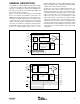
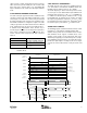
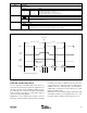
AUDIO DATA FORMATS
The DIT4096 supports standard audio data formats, includ-
ing Philips I
2
S, Left-Justified, and Right-Justified data.
Software mode provides the most flexible format selection,
while Hardware mode supports a limited subset of the
Software mode formats. Linear PCM audio data at the
SDATA input is typically presented in Binary Two’s Comple-
ment, MSB first format. Encoded or non-audio data may be
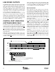
provided as required by the encoding scheme in use. Figure
4 shows the common data formats used by the audio serial
port.
t
SYNCHL
t
SYNCHL
t
SYSK
t
SYSKHL
t
SCLKHL
t
SCLKP
t
ADS
t
ADH
MSB LSB
MSB LSB
MSB LSB
MSB LSB
MSB LSB
MSB LSB
Right Justified
Left Justified
0 SCLK Delay
Left Justified
1 SCLK Delay (I
2
S)
Right ChannelLeft Channel
SYNC
(ISYNC = 0)
SYNC
(ISYNC = 1)
SCLK
(ISCLK = 0)
SCLK
(ISCLK = 1)
SYNC
SCLK
SDATA
SDATA
SDATA
SDATA
FIGURE 4. Audio Data Formats and Timing.