
Datasheet


DIT4096
8
SBOS225A
www.ti.com
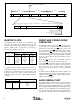
AUDIO DATA
FORMATS
CONTROL REGISTER 03
H
BIT SETTINGS
Bit Name Function Bit Name Function Bit Name Function Bit Name Function
JUS Justification DELAY SCLK Delay ISCLK Sampling Edge ISYNC Phase
Phillips I
2
S 0 Left-Justified 1 1 SCLK Delay 0 Rising Edge 1 Inverted
Left-Justified 0 Left-Justified 0 0 SCLK Delay 0 Rising Edge 0 Noninverted
Right-Justified 1 Right-Justified 0 0 SCLK Delay 0 Rising Edge 0 Noninverted
TABLE IV. Audio Data Format Selection in Software Mode.
For Software mode, Control Register 03
H
is used to set the
audio data format selection. Data word length may be set to
16, 18, 20, or 24 bits using the WLEN0 and WLEN1 bits.
Several format parameters, including SCLK sampling edge,
data delay from the start of frame, and SYNC polarity may be
programmed using this register. Table IV shows examples of
register bit settings for three standard audio formats. SCLK
sampling edges and SYNC polarity may differ from one
system implementation to the next. Consult the audio source
device data sheet or technical reference for details regarding
the output data formatting.
For Hardware mode, the FMT0 (pin 9) and FMT1 (pin 10)
inputs are utilized to select one of four audio data formats.
Refer to Table V for the available format selections.
INPUT PINS
FMT1 FMT0
FORMAT SELECTIONS
0 0 24-Bit Left-Justified
0 1 24-Bit I
2
S
1 0 24-Bit Right-Justified
1 1 16-Bit Right-Justified
TABLE V. Audio Data Format Selection for Hardware Mode.
AES-3 ENCODER OPERATION
The AES-3 encoder performs the multiplexing of audio,
channel status, user, and validity data. It also performs Bi-
Phase Mark encoding of the multiplexed data stream. This
section describes how channel status, user, and validity data
are input to the encoder function.
BLOCK START INPUT/OUTPUT
The block start is used to indicate the start of a channel status
data block, which starts with Frame 0 for the AES-3 data
stream. For the DIT4096, the block start signal, BLS
(pin 25), may be either an input or output. In Software mode,
the direction of BLS is set using the BLSM bit in control register
01
H
(defaults to input). In Hardware mode, the direction of BLS
is set by the BLSM input (pin 24). If BLSM = 0, the BLS pin is
an input. If BLSM = 1, the BLS pin is an output.
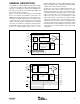
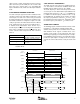
For Software mode operation, the block start signal is syn-
chronized to the audio serial port frame sync clock, SYNC
(pin 12). When BLS is configured as an input pin, it is
sampled on the rising edge of SYNC when the ISYNC bit in
control register 03
H
is set to 0. Otherwise, it is sampled on the
falling edge of SYNC when the ISYNC bit is set to 1. If BLS
is high when it is sampled, then a block start condition is
indicated. When BLS is configured as an output and the
ISYNC bit is set to 0, BLS will go high at every 192nd falling
edge of SYNC for Stereo mode, or every 384th falling edge
of SYNC for Mono mode. BLS will then go low on the
following falling edge. If the ISYNC bit is set to 1, then BLS
transitions on the rising edge of SYNC.
Hardware mode operation is similar to Software mode opera-
tion, with the exception that there are only a limited number
of data formats available for the audio serial port. For Left-
and Right-Justified formats, BLS behaves as it would in
Software mode with ISYNC = 0. For the I
2
S data format, BLS
behaves as it would in Software mode with ISYNC = 1.
CHANNEL STATUS DATA INPUT
Channel status data input is determined by the control mode
in use. In Software mode, the channel status data buffer is
accessed through the serial control port. Buffer operations
are described in detail in the section of this data sheet
entitled Channel Status Buffer Operation (Software Mode
Only). In Hardware mode, channel status data input is
accomplished by one of two user-selectable methods.
THE CSS INPUT
In Hardware mode, the state of the CSS input (pin 1)
determines the function of dedicated channel status inputs.
When CSS = 0, the COPY (pin 2), L (pin 3),
AUDIO
(pin 22),
and
EMPH
(pin 23) inputs are used to set associated
channel status data bits. The COPY and L inputs are used to
setup copy protection for consumer operation, or indicate
that the transmitter is operating in professional mode, without
copy protection. The
AUDIO
input is utilized to indicate
whether the data being transmitted is PCM audio data, or
non-audio data. The EMPH
input is used to indicate whether
the PCM audio data has been pre-emphasized using the
50/15µs standard. See Table VI for the available options for
these dedicated channel status inputs.
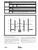
When CSS = 1, the channel status data is input in a serial
fashion at the C input (pin 2). Data is clocked on the rising
and falling edges of the SYNC input (pin 12). All channel
status data bits can be written in this mode, allowing greater
flexibility than the previous Hardware mode case with
CSS = 0. See Figure 5 for the C input timing diagram.