
Datasheet


DIT4096
9
SBOS225A
www.ti.com
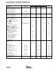
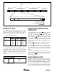
INPUT FUNCTION
COPY Copy Status
L Generation Status
COPY L Status
0 0 Consumer Mode, PRO = 0, COPY = 0, L = 0
0 1 Consumer Mode, PRO = 0, COPY = 0, L = 1
1 0 Consumer Mode, PRO = 0, COPY = 1, L = 0
1 1 Professional Mode, PRO = 1, No Copy Protection
AUDIO Audio Data Status
AUDIO Status
0 Digital (or Linear PCM) Audio Data.
1 Non-Audio or Encoded Audio Data.
EMPH Pre-Emphasis Status
EMPH Status
0 Pre-emphasis bits are set to indicate 50/15µs Pre-emphasis has been applied.
1 Pre-emphasis bits are set to indicate that no Pre-emphasis has been applied.
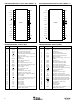
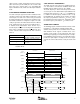
Frame 191 or 383 Frame 0
Block Start
SYNC
(1)
BLS
(Input)
BLS
(Output)
C, U, or V
Data
NOTE: (1) Assumes ISYNC = 0.
t
CUVS
t
CUVH
Ch B
Data
Ch A
Data
Ch B
Data
Ch A
Data
192nd or 384th
Falling Edge
(1)
TABLE VI. Channel Status Data Input for Hardware Mode with CSS = 0.
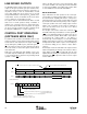
FIGURE 5. C, U, and V Data Timing.
USER AND VALIDITY DATA INPUT
The user data bits in the AES-3 data stream allow for a
convenient way to transfer user-defined or application spe-
cific data to another device containing an AES-3 receiver.
The U input (pin 27) is used in both Software and Hardware
mode to input the user data in a serial fashion. Figure 5
shows the U input timing diagram.
Validity data is used to indicate that a sample is error-free
audio data, or that the sample is defective and is not suitable
for further processing. In Software mode, the VAL bit in
control register 01
H
is utilized to write the validity data. In
Hardware mode, the V input (pin 26) is used to input the
validity data in serial fashion. Refer to Figure 5 for V input
timing for Hardware Mode.
When VAL or V = 0, this indicates that the audio data is valid
and suitable for further processing. When VAL or V = 1, then
the audio sample is defective and should not be used.