
Datasheet

www.ti.com
SN74LVC1G125
orEquivalent
0.1mF
T RX+o
ToRX-
From+5VLogic
(TTLorCMOS)
VDD33
5
2
3
1
4
SN74AVC1T45
orEquivalent
0.1mF
T RX+o
ToRX-
From+1.8Vor+2.5V
CMOSLogic
+1.8Vor+2.5V
5
VDD33
6
3
1
2
4
TRANSMITTER OUTPUT INTERFACING
1:1
0.1 Fm
TX+
TX-
3
2
1
XLR
DigitalOutput
110 BW alanced
110W
DIX4192
SBFS031C – JANUARY 2006 – REVISED JUNE 2006
APPLICATIONS INFORMATION (continued)
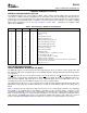
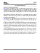
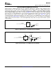
The DIX4192 line receivers may also be driven directly from external logic or line receiver devices with TTL or
CMOS outputs. If the logic driving the line receiver is operated from +3.3V, then logic level translation will not be
required. However, if the external logic is operated from a power-supply voltage that exceeds the maximum
VDD33 supply voltage of the DIX4192, or operates from a supply voltage lower than +3.3V, then level
translation is required. Figure 29 shows the recommended logic level translation methods, utilizing buffers and
level translators available from Texas Instruments.
Figure 29. CMOS/TTL Input Logic Interface
This section details the recommended interfaces for the DIX4192 transmitter line driver and CMOS-buffered
outputs. Balanced and unbalanced line interfaces, in addition to optical transmitter and external logic interfacing,
will be discussed.
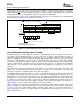
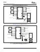
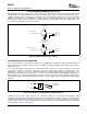
For professional digital audio interfaces, 110 Ω balanced line interfaces are either required or preferred.
Transformer coupling is commonly employed to provide isolation and to improve common-mode noise
performance. Figure 30 shows the recommended transformer-coupled balanced line driver interface for the
DIX4192. The transformer is specified for a 1:1 turn ratio, and should exhibit low inter-winding capacitance for
best performance. To eliminate residual DC bias, a 0.1 µ F capacitor is utilized for AC-coupling the transformer to
the line driver outputs. The coupling capacitor should be a surface-mount ceramic chip type with an X7R or C0G
dielectric.
Figure 30. Transformer-Coupled Balanced Output Interface
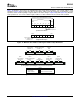
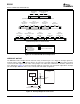
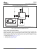
Unbalanced 75 Ω coaxial cable interfaces are commonly employed in consumer and broadcast audio
applications. Designs with and without transformer line coupling may be utilized. Figure 31 (a) illustrates the
recommended 75 Ω transformer-coupled line driver interface, which shares many similarities to the balanced
design shown in Figure 30 . Figure 31 (b) illustrates the transformer-free line driver interface, which is commonly
used for S/PDIF consumer connections.
30
Submit Documentation Feedback