
Owner's manual

2.6 EDMA Event Support
2.7 Power Management
2.8 Emulation Considerations
3 Registers
www.ti.com
Registers
The ADC interface module does not generate an EDMA event.
The ADC interface can be placed in reduced-power modes to conserve power during periods of low
activity. Power management of the ADC Interface is controlled by the power and sleep controller (PSC)
processor. The PSC acts as a master controller for power management for all of the peripherals on the
device. For detailed information on power management procedures using the PSC, see the
TMS320DM365 Digital Media System-on-Chip (DMSoC) ARM Subsystem Reference Guide (SPRUFG5 )
ADC interface supports the emulation suspend function. At the enable emulator suspend, this module
keep the following condition and restart.
• Stop after a A-D convert
• Bus access is available under the suspend time
• Restart with the setting condition after the suspend time
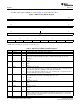
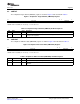
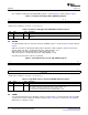
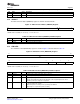
Table 1 lists the memory-mapped registers for the analog-to-digital Controller (ADC) interface. See the
device-specific data manual for the memory address of these registers
Table 1. ADC interface Memory Map Registers
Offset Register Description Location
0x0 ADCTL Control register Section 3.1
0x4 CMPTGT Comparator target channel Section 3.2
0x8 CMPLDAT Comparison A/D Lower data Section 3.3
0xC CMPUDAT Comparison A/D Upper data Section 3.4
0x10 SETDIV SETUP divide value for start Section 3.5
A/D conversion
0x14 CHSEL Analog Input channel select Section 3.6
0x18 AD0DAT A/D conversion data 0 Section 3.7
0x1C AD1DAT A/D conversion data 1 Section 3.8
0x20 AD2DAT A/D conversion data 2 Section 3.9
0x24 AD3DAT A/D conversion data 3 Section 3.10
0x28 AD4DAT A/D conversion data 4 Section 3.11
0x2C AD5DAT A/D conversion data 5 Section 3.12
0x30 EMUCTRL Emulation Control Section 3.13
SPRUFI7 – March 2009 Analog to Digital Converter (ADC) Interface 11
Submit Documentation Feedback