
Owner's manual

3.2 CMPTGT
3.3 CMPLDAT
www.ti.com
Registers
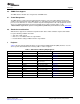
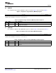
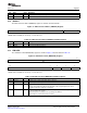
The comparator target channel (CMPTGT) register is shown in Figure 3 and described in Table 3 .
Figure 3. Comparator Target Channel (CMPTGT) Register
31 6 5 0
Reserved CMPTGT
R-0 R/W-0
LEGEND: R/W = Read/Write; R = Read only; - n = value after reset
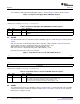
Table 3. Comparator Target Channel (CMPTGT) Field Descriptions
Bit Field Value Description
31-6 Reserved 1 0 Any writes to these bit(s) must always have a value of 0.
5-0 CMPTGT Comparator target channel at A/D conversion The analog input that has written ‘1’ into CMPTGT is
the target of the comparator.
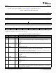
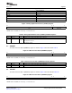
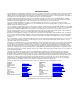
The comparison A/D lower data (CMPLDAT) register is shown in Figure 4 and described in Table 4 .
Figure 4. Comparison A/D Lower Data (CMPLDAT) Register
31 10 9 0
Reserved CMPLDAT
R-0 R/W-0
LEGEND: R/W = Read/Write; R = Read only; - n = value after reset
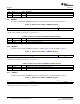
Table 4. Comparison A/D Lower Data (CMPLDAT) Field Descriptions
Bit Field Value Description
31-10 Reserved 0 Any writes to these bit(s) must always have a value of 0.
9-0 CMPLDAT Comparative data (lower) value of CMPLDAT should be the same as or smaller than that of
CMPUDAT.
SPRUFI7 – March 2009 Analog to Digital Converter (ADC) Interface 13
Submit Documentation Feedback