
Owner's manual


Preface
SPRUFI7 – March 2009
Read This First
About This Manual
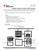
This document describes the analog-to-digital converter (ADC) interface peripheral in the TMS320DM36x
Digital Media System-on-Chip (DMSoC).
Notational Conventions
This document uses the following conventions.
• Hexadecimal numbers are shown with the suffix h. For example, the following number is 40
hexadecimal (decimal 64): 40h.
• Registers in this document are shown in figures and described in tables.
– Each register figure shows a rectangle divided into fields that represent the fields of the register.
Each field is labeled with its bit name, its beginning and ending bit numbers above, and its
read/write properties below. A legend explains the notation used for the properties.
– Reserved bits in a register figure designate a bit that is used for future device expansion.
Related Documentation From Texas Instruments
The following documents describe the TMS320DM36x Digital Media System-on-Chip (DMSoC). Copies of
these documents are available on the internet at www.ti.com .
SPRUFG5 — TMS320DM36x Digital Media System-on-Chip (DMSoC) ARM Subsystem Users Guide
This document describes the ARM Subsystem in the TMS320DM36x Digital Media System-on-Chip
(DMSoC). The ARM subsystem is designed to give the ARM926EJ-S (ARM9) master control of the
device. In general, the ARM is responsible for configuration and control of the device; including the
components of the ARM Subsystem, the peripherals, and the external memories.
SPRUFG8 — TMS320DM36x Digital Media System-on-Chip (DMSoC) Video Processing Front End
(VPFE) Users Guide This document describes the Video Processing Front End (VPFE) in the
TMS320DM36x Digital Media System-on-Chip (DMSoC).
SPRUFG9 — TMS320DM36x Digital Media System-on-Chip (DMSoC) Video Processing Back End
(VPBE) Users Guide This document describes the Video Processing Back End (VPBE) in the
TMS320DM36x Digital Media System-on-Chip (DMSoC).
SPRUFH0 — TMS320DM36x Digital Media System-on-Chip (DMSoC) 64-bit Timer Users Guide This
document describes the operation of the software-programmable 64-bit timers in the
TMS320DM36x Digital Media System-on-Chip (DMSoC). Timer 0, Timer 1, and Timer 3 are used
as general-purpose (GP) timers and can be programmed in 64-bit mode, dual 32-bit unchained
mode, or dual 32-bit chained mode; Timer 2 is used only as a watchdog timer. The GP timer modes
can be used to generate periodic interrupts or enhanced direct memory access (EDMA)
synchronization events and Real Time Output (RTO) events (Timer 3 only). The watchdog timer
mode is used to provide a recovery mechanism for the device in the event of a fault condition, such
as a non-exiting code loop.
SPRUFH1 — TMS320DM36x Digital Media System-on-Chip (DMSoC) Serial Peripheral Interface (SPI)
Users Guide This document describes the serial peripheral interface (SPI) in the TMS320DM36x
Digital Media System-on-Chip (DMSoC). The SPI is a high-speed synchronous serial input/output
port that allows a serial bit stream of programmed length (1 to 16 bits) to be shifted into and out of
the device at a programmed bit-transfer rate. The SPI is normally used for communication between
the DMSoC and external peripherals. Typical applications include an interface to external I/O or
peripheral expansion via devices such as shift registers, display drivers, SPI EPROMs and
analog-to-digital converters.
SPRUFI7 – March 2009 Preface 5
Submit Documentation Feedback