
Datasheet


DRV110
www.ti.com
SLVSBA8A –MARCH 2012–REVISED JANUARY 2013
POWER SAVING SOLENOID CONTROLLER WITH INTEGRATED SUPPLY REGULATION
Check for Samples: DRV110
1
FEATURES
• Drives an External MOSFET With PWM to – External Pull-Up Resistor to Solenoid
Control Solenoid Current Supply Voltage
– External Sense Resistor for Regulating • Protection
Solenoid Current
– Thermal Shutdown
• Fast Ramp-Up of Solenoid Current to
– Under Voltage Lockout (UVLO)
Guarantee Activation
– Maximum Ramp Time
• Solenoid Current is Reduced in Hold Mode for
– Optional STATUS Output
Lower Power and Thermal Dissipation
• Operating Temperature Range: -40ºC to 105ºC
• Ramp Peak Current, Keep Time at Peak
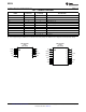
• 8-Pin and 14-Pin TSSOP Package Options
Current, Hold Current and PWM Clock
Frequency Can Be Set Externally. They Can
APPLICATIONS
Also Be Operated at Nominal Values Without
• Electromechanical Driver: Solenoids, Valves,
External Components.
Relays
• Internal Supply Voltage Regulation
• White Goods, Solar, Transportation
– 15-V Nominal MOSFET Gate Drive Voltage
DESCRIPTION
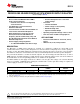
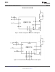
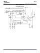
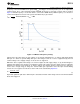
The DRV110 is a PWM current controller for solenoids. It is designed to regulate the current with a well
controlled waveform to reduce power dissipation. The solenoid current is ramped up fast to ensure opening of
the valve or relay. After initial ramping the solenoid current is kept at peak value to ensure the correct operation,
after which it is reduced to a lower hold level in order to avoid thermal problems and reduce power dissipation.
The peak current duration is set with an external capacitor. The current ramp peak and hold levels, as well as
PWM frequency can independently be set with external resistors. External setting resistors can also be omitted, if
the default values for the corresponding parameters are suitable for the application.
The DRV110 limits its own supply at VIN to 15 V which is also the gate drive voltage of an external switching
device. For example, a MOSFET that is driving the solenoid load. If a lower gate drive voltage is required, an
external supply of at least 6 V can be used.
ORDERING INFORMATION
(1)
ORDERABLE PART TOP-SIDE
PACKAGE
(2)
NUMBER MARKING
(TSSOP-8) - PW Reel of 2000 DRV110PWR 110
(TSSOP-14) - PW Reel of 2000 DRV110APWR 110A
(1) For the most current packaging and ordering information, see the Package Option Addendum at the end of this document, or see the TI
web site at www.ti.com.
(2) Package drawings, thermal data, and symbolization are available at www.ti.com/packaging.
1
Please be aware that an important notice concerning availability, standard warranty, and use in critical applications of
Texas Instruments semiconductor products and disclaimers thereto appears at the end of this data sheet.
PRODUCTION DATA information is current as of publication date.
Copyright © 2012–2013, Texas Instruments Incorporated
Products conform to specifications per the terms of the Texas
Instruments standard warranty. Production processing does not
necessarily include testing of all parameters.